Active balancer for 13s?

Cyclomania

10 kW
Joined
May 22, 2022
Messages
715
Location
Northern Europe
So after disconnecting the BMS from my faulty battery it seems I again get a more correct reading. But it seems the cell groups are now 3,4 or 3,5 and one of the 13 cell groups is at 3,2. Issue that arose with this battery was that it was showing 37 volts of charge, when the bms was still connected. But when it is now separated from the balance leads the main negative and positive show a more correct reading of 43 volts for the entire pack.

Can I use an active balancer, made for a 13s-pack, to charge back my cell groups into balance again?
And after that I could try to connect the balance wire-connector(now separated from the BMS) back into the BMS again?
Or do I have to disassemble the cell groups not in balance and balance every cell individually?
 
A good 14S BMS with top balance circuits will be able to resolve your difference between cell groups. It might require leaving the battery on charge for a day or two. Takes a while. They could probably do bigger differences if you were willing to wait a week or more.

Top balance means it doesn't start balancing til the first cell group hits full charge, Then it bleeds charge off that group til the next one gets to full charge, THen it bleeds these two til the third one comes up. On and on till all 14 are there. WHile this is happening, the charger light is red because charge current is very small. I suspect that they will keep this bleed/balance up until you disconnect the charger, A smart BMS probably shuts off. but there's not a lot of smarts in a dunb BMS.
How would you go about doing this and where can I find one of those BMSes?
Do you mean to hook it up first to the top balance-BMS, then charge the battery up with a normal charger, or the other way around? First hook up to BMS like it is now, unbalanced, and then charge the battery with a normal charger?

I thought maybe if I connected the balance wires back into a BMS now, since they are not in total balance, it would lead to heat and potential sparks? So not entirely sure how you mean. By the way do you have a link to one of those on Ali, Amazon, Temu or something?
Would something like this work: https://www.aliexpress.com/item/1005003651719120.html?spm=a2g0o.detail.0.0.56b285b9iCyu4V&mp=1

thanks
 
You remove the old BMS and put on a working one.

Look for a JBD BMS if you want to view info on an App, or a real Daly BMS. I believe those Superior BMS are copies of Daly BMS. Popular products, doesn't even matter if they are any good, get copied in CHina,
 
You remove the old BMS and put on a working one.

Look for a JBD BMS if you want to view info on an App, or a real Daly BMS. I believe those Superior BMS are copies of Daly BMS. Popular products, doesn't even matter if they are any good, get copied in CHina,
Hmm, so the Daly BMS or something similar, that has top circuits, will basically be able to handle the different voltages between the cell groups in contrast to a more cheap BMS? I can just plug in the balance leads, despite the voltage difference when I am using one of those?

That is interesting. Is that because they do not bleed voltages passive over time by using heat, or how are they able to do this in contrast to a cheaper older version BMS?
 
I have now tried the active balancer that balanced the groups a lot more in line. Shows 43 volts on main negative and positive. Strange thing I thought now I could reconnect the bms. But when the BMS is reconnected everything shows 37 volts again on the main negative and plus. So quite strange.

Any idea why it breaks down again when the BMS is reconnected?
 
You remove the old BMS and put on a working one.

Look for a JBD BMS if you want to view info on an App, or a real Daly BMS. I believe those Superior BMS are copies of Daly BMS. Popular products, doesn't even matter if they are any good, get copied in CHina,

I am waiting for a new one but I have this one in this link already at home. 40 amps. Do you think it could work or should I wait for the really good one that is coming in the mail instead?

I need to solder on new balance leads so a bit of work to do if it does not work anyway. But do you think this one could work?
 
I ordered one from the same vendor this year. The Annpower one worked for me.
Great. So now I do not want to do this in the wrong order hopefully. Which cable do you solder on first of the BMS? Do you first solder on the main negative before the balance leads or the other way around? I cannot remeber exactly how this was done when I messed with this in the past.

I guess:

step 1: disconnect main negative of the old bms
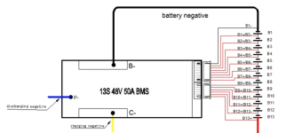
step 2: solder on main negative from the new bms to battery main negative
step 3: disconnect charging cable of old bms
step 4: solder on new charging cable to the same output as the one before from the new bms
step 5: solder on balance wires
step 6: check voltage of cell groups
step 7: put the connector from the balance wires into the bms

Sounds all right?
 
Be careful and don't short circuit anything,

When you check the voltages, make sure they go up in sequence B1-B13, It's very easy to get the wires out of sequence. Take your time, measure the cell tab voltage to make sure it's the right one before you connect the next balance wire.


.
 
Last edited:

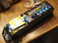
So I have done the worst now. The BMS is connected and the pack seems to be working fine contrary to before. So maybe the issue was the BMS all along? But now I soldered these wires a bit clumsy so I basically have to have them on top of each other during the first centimeters going out of the BMS.

I am going to place the BMS as the video here. So the balance leads will have to go over each other somewhat in the first centimeters coming out of the BMS. I know this is not ideal for safety reasons to have them cross each other that much. But I think I have to do it if I want it to fit where it is now, on the side there.

The Balance wires were not as long as I first thought, so they will basically have to sit like this. Perhaps I could put some hot glue on them, in the beginning where they are turning a lot over each other? First centimeters out of the BMS. To isolate them a bit from each other. What do you think? Just to make sure they do not short each other while the battery falls off the bike or something. See vid.
It won't be pretty but at least they would not move a lot. And this will not be visible once the case is in place.

I plan on placing/gluing the BMS exactly where it is in the video. Because that is now the best spot inside the case, since the BMS is also rather big. This place is obviously not ideal because of the balance leads crossing each other so much. But could I just hot glue them there to the side perhaps? To make them stick to each other but at the same time not AT each other. So they are separated a bit by the hot glue.
 
Last edited:
Have you tested it? Looks like the BMS has on/off wires and thermocouple.
-If you turn the BMS on/off do you see the battery voltage come/go on the battery output?
-Is the output about the same as the cell stack?
-Will it charge and balance to the full 54.6V or close to it?

Dressing the wires is usually something you try to do when laying down the wires. With the balance taps are on both sides, you can't lay them out without crossing wires. Some people use yellow kapton tape as an insulator in case the balance wires were to get hot. I suspect these wires would melt if they were to short out a cell group.

RB200806.JPG
 
Hmm on and off wires and thermocouple? I can only see the B minus(fat black one: soldered onto the first negative cell group) that goes form the first negative cell-group to which it is soldered then on to the bms, P minus (blue cable) goes out of the BMS to my main negative discharge port going out of the battery and C for charging(thinner black wire in the middle between the two fat ones). Which ones are the On and Off wires do you mean?

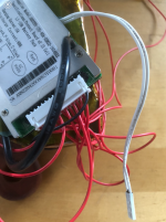
The small white ones are for temperature sensor(which is what you mean when you say thermocouple probably?) that should be fastened to a cell I think. For measuring heat or something.
Here it is: https://www.aliexpress.com/item/330...7*MTczMTUxNTQ0NS43LjEuMTczMTUxNjE0NC42MC4wLjA.
The 40a BMS.

I am thinking that either I have made a mistake and the BMS shut down somehow. But should it not be showing 36-37 volts again then, when checking the terminals? As the old BMS did. But since it is not connected(I think?) and showing around 44 volts maybe it works ?

Or the BMS is not doing anything. Just leading current through it in contrast to the old one. And therefore showing 44 volts but at the same item not functioning(?) Is there a way for me to check if the BMS is actually doing anything?
 

Attachments

  • pic1.png
    pic1.png
    328.8 KB · Views: 3
  • pic2.png
    pic2.png
    99.6 KB · Views: 3
Last edited:
Thought I saw in one of your pics, a double black for the thermocouple, but if you don't have an ON/OFF switch. then it's always ON,

So what's the output voltage red battery wire to P- on discharge connector? Should be same as red wire to B-,

Connect it to your bike and see if it spins the wheel. Then charge it up. Give it some tome to balance and see how even it is, If it;s OK, put it in the case.
 
Thought I saw in one of your pics, a double black for the thermocouple, but if you don't have an ON/OFF switch. then it's always ON,
It looks like this the thermocouple. Byt the way do you know if the text side should be against a cel or the other way around?
 

Attachments

  • thermocouple.png
    thermocouple.png
    1.3 MB · Views: 5
So what's the output voltage red battery wire to P- on discharge connector? Should be same as red wire to B-,

Connect it to your bike and see if it spins the wheel. Then charge it up. Give it some tome to balance and see how even it is, If it;s OK, put it in the case.
I have measured a couple of ways. Like from battery minus inside the case to main dicharge port +. Then the other way around. They all show 46,1 volts now. I also tried charging it a bit, which is the reason it is now at 46,1 volts and not 44 anymore.

So I guess this means I am good to go perhaps? Just close the case? Or should I do some other test?
 
Charge it to full and see if the cells are equalized. Unless this is a blue tooth BMS, you need the case open to check the 13 groups.
 
Charge it to full and see if the cells are equalized. Unless this is a blue tooth BMS, you need the case open to check the 13 groups.
Hmm charge it to full and thendisconnect the BMS you mean? And check inside the pin connector if the cell groups ll have the same voltages and increase at the same rate? That is what you mean correct?
 
Charge it to full and see if the cells are equalized. Unless this is a blue tooth BMS, you need the case open to check the 13 groups.
I have rode the bike with this pack. Not completely fully charged yet but it all seems to work now.
When charging it full it should go up to 54,6 correct? I think this is the correct voltage for 48 volt packs correct?

Are you good at explaining the function of the BMS too? What this will do is balance the pack over time as well is that right? I've heard this can take several months though?
 
Last edited:
The typical balance BMS does it at the end of the charge cycle when the battery is almost charged,

With your thirteen cell groups, as soon as one of them reach the balance volt around 4.20V, a small resistor is switched across the cell group to slowly discharge it. The charger usually switches from red to green, but it is still applying voltage to charge the other groups so they keep increasing,

When the next group reaches 4.20 volts, it also goes into balance mode. So you have two groups discharging. Eventually all thirteen groups are in balance mode. You don't know this is happening or when it stops, The charger LED is green. This can take a few hours. If the cell groups are far apart, it can take days,

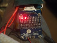
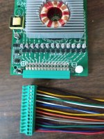
So I got this BMS with LEDs. It has a visual indicator for all the groups. When that bank has reached balance voltage, it lights up, The bleed resistors, which are just below the LED start discharging. You can see which groups are balancing. This picture shows banks 2 and 4 are in balance mode.

PC061256.JPG

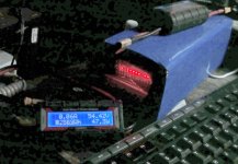
This next battery pic shows two groups not fully charged. I have a wattmeter connected to the charger. It says the battery is above 54V, with a small charge current of .06 amps coming out of the charger. The total power that went back into the battery is 8.6 AH.

P1200153.jpg

Eventally, all the LED's light up. The BMS has some quirks, but I think they apply to most balance BMS without LED's. It doesn't work with really cheap chargers. Those chargers shut down at low currents used for balancing. It also can't tell when the battery is balanced and keeps bleeding, even after the charger is unplugged,

I put the BMS in a few shrinkwrapped packs, but it's not useful if you have a case, DOesn't have an on/off switch so another reason not to use it in a case, Quality may not be that good. I had a couple that didn't work, but that may be due to static discharge from careless handling, Most BMS, like yours, have a metal plate over the circuitry. I seem to blow up a lot of these BMS that are just bare.
 
The typical balance BMS does it at the end of the charge cycle when the battery is almost charged,

With your thirteen cell groups, as soon as one of them reach the balance volt around 4.20V, a small resistor is switched across the cell group to slowly discharge it. The charger usually switches from red to green, but it is still applying voltage to charge the other groups so they keep increasing,

When the next group reaches 4.20 volts, it also goes into balance mode. So you have two groups discharging. Eventually all thirteen groups are in balance mode. You don't know this is happening or when it stops, The charger LED is green. This can take a few hours. If the cell groups are far apart, it can take days,

So I got this BMS with LEDs. It has a visual indicator for all the groups. When that bank has reached balance voltage, it lights up, The bleed resistors, which are just below the LED start discharging. You can see which groups are balancing. This picture shows banks 2 and 4 are in balance mode.

View attachment 361937

This next battery pic shows two groups not fully charged. I have a wattmeter connected to the charger. It says the battery is above 54V, with a small charge current of .06 amps coming out of the charger. The total power that went back into the battery is 8.6 AH.

View attachment 361939

Eventally, all the LED's light up. The BMS has some quirks, but I think they apply to most balance BMS without LED's. It doesn't work with really cheap chargers. Those chargers shut down at low currents used for balancing. It also can't tell when the battery is balanced and keeps bleeding, even after the charger is unplugged,

I put the BMS in a few shrinkwrapped packs, but it's not useful if you have a case, DOesn't have an on/off switch so another reason not to use it in a case, Quality may not be that good. I had a couple that didn't work, but that may be due to static discharge from careless handling, Most BMS, like yours, have a metal plate over the circuitry. I seem to blow up a lot of these BMS that are just bare.
So realistically it would be best to charge it up full? Until it turns green right? Then the balancing should begin? If everything works as it should do right?
 
I normally have a habit of not charging batteries full because I have heard that this hurts the cells over time. But for this purpose it would be good to charge it up full and leave it there for a couple of days right?
 
When the next group reaches 4.20 volts, it also goes into balance mode. So you have two groups discharging. Eventually all thirteen groups are in balance mode. You don't know this is happening or when it stops, The charger LED is green. This can take a few hours. If the cell groups are far apart, it can take days,
I have charged it up full to green light. Only goes to 53,3 it seems. Any idea what it means?
 
I have charged it up full to green light. Only goes to 53,3 it seems. Any idea what it means?
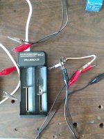
The battery is out of balance.I manually balanced using a bulb to discharge the high groups and IMG_20241117_085144669.jpgIMG_20241117_083558463.jpgcharged the lower groups.It takes many hours with constant supervision to manually balance.I bought a active balancer.
 
The battery is out of balance.I manually balanced using a bulb to discharge the high groups and View attachment 361958View attachment 361959charged the lower groups.It takes many hours with constant supervision to manually balance.I bought a active balancer.
Hmm ok. Thing is I also used an active balancer. So I am not sure what is wrong now. I did balance the groups when it was around 44 volts. Putting the connector pin of the BMS into the active balancer. When it was balanced I put it in the BMS which is on the battery now. Then I taped it up and closed the case. Then I charged it up and it is now at 53,3 at full charge.

Any idea what this means? Did it become unbalanced during the charging process then?

It seems like the battery works when I put it on the bike. But maybe I should not ride it in this condition then?
 
Back
Top