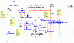
Hello, these days I am evaluating improved circuit, and I found Your thread interesting. I would like to contribute to the idea with my schematic. It only needs a simple switch, everything else is done automatically. Take it as an idea, I know some components needs to be replaced with appropriate ones. This was for rough simulation if it is going to work. The capacitors in upper part represents capacitance in controller. With these components it should work from 48V to 72V batteries (power mosfets to be replaced with better ones according to findings in this thread).
You are using an out of date browser. It may not display this or other websites correctly.
You should upgrade or use an alternative browser.
You should upgrade or use an alternative browser.
Active pre-charge/inrush control
- Thread starter boo
- Start date
I also use an on/on switch which toggles GATE between GND and Battery + (1mOhm resisitor in this supply line). It works well and i never had problems with it.
Now i want to improve a few things on my bike and i want to make sure this switch will not do any stupid things if water comes to the contacts or somewhere else..
Following situations:
switch is in "OFF" position so GATE line is connected direct to GND (without resisitor) => should be waterproof
switch is in "ON" position so GATE line is connected to battery + with 1mOhm resisitor in it => now if water comes to the contacts, could it be that GATE line will be pulled down so much its more near GND than Battery + ?
I know with 90V+ on the switch it cannot be really waterproof because of electrolysis processes, but i want to be sure it doesn't do unwanted things.
Should i bother if i ride in rain or wet conditions with this circuit?
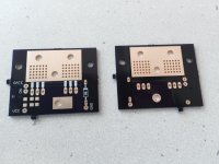
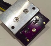
btw: nice boards izeman
There could be also used on/on switch in my circuitry. It would gain some extra reliability if some water/moisture gets to the contacts. But it would be also advidsable not to allow moisture/water get in there, as it would cause corrosion and corroded contacts are not what we need. In my case it looks like better scenario with corroded contacts, high voltage should pass through and grounding connection don´t need to be perfect, the circuit discharges the gate capacitor rapidly either way. I assume that corroded contact would have far less resistance than water/moisture between the other two contacts.
madin88 said:Following situations:
switch is in "OFF" position so GATE line is connected direct to GND (without resisitor) => should be waterproof
switch is in "ON" position so GATE line is connected to battery + with 1mOhm resisitor in it => now if water comes to the contacts, could it be that GATE line will be pulled down so much its more near GND than Battery + ?
I know with 90V+ on the switch it cannot be really waterproof because of electrolysis processes, but i want to be sure it doesn't do unwanted things.
Should i bother if i ride in rain or wet conditions with this circuit?
btw: nice boards izeman
The switch should really only have 12v on it, limited by the zener diode. In rain, it could be possible for the gate voltage to get pulled down, which could make the FETs turn off. It would be bad if they got only partially pulled down to the point where the FETs are half on, causing massive heating. You'd notice a big loss of power and hopefully the LVC in the controller would kick in before anything burned up. It's hard to make everything completely bulletproof.
thanks. there are really only 12V or zener voltage on the switch in "ON" position. thats good because the lower the voltage, the less current will flow between contacts if they got wet - right?
in off position battery voltage is on the open contact but as GATE is connected directly to GND this will not make problems.
what about using 100kOhm or 10kOhm and use a larger cap to have same precharge time?
in off position battery voltage is on the open contact but as GATE is connected directly to GND this will not make problems.
what about using 100kOhm or 10kOhm and use a larger cap to have same precharge time?
Yes, you could use a larger cap and smaller resistor to get the same charge time but at a higher current that would be less prone to water effects. At 10k, the resistor might start getting hot unless you use a higher wattage one. I wouldn't go less than 10k.
izeman
1 GW
izeman
1 GW
Nice looking boards 8)
That chunk of aluminum should work great for keeping the FETs cool.
That chunk of aluminum should work great for keeping the FETs cool.
good job!
i have seen controllers using the precharge FETs also as shunt. would this work on this circuit?
the resisitance of FET's certainly will vary more and have more temperature drift, but i think for this purpose it could be accurate enough since they will not get much above ambient temperature.
i have seen controllers using the precharge FETs also as shunt. would this work on this circuit?
the resisitance of FET's certainly will vary more and have more temperature drift, but i think for this purpose it could be accurate enough since they will not get much above ambient temperature.
izeman
1 GW
good question. maybe worth investigating. but for me it's not worth it, as i think this setup will be all i need for now and for the future. and the 5mohm shunt is big enough to handle 50A easily.
izeman
1 GW
they work absolutely perfect. no issues so far. and it's very simple as well. the FET does what it's made for. switching. 
if you want you can have a board. i have some spares left. they will take 2x FETs.
if you want you can have a board. i have some spares left. they will take 2x FETs.
I'm based in Australia. But I'll gladly take one off your hands. Pm me the cost and I'll sort it out.
I may do a run of these boards myself. What's the best way to go about ordering 10 or so?
I'll be using them in skateboards would there be a way to make them even more compact. While still retaining a decent amperage rating?
Cheers
I may do a run of these boards myself. What's the best way to go about ordering 10 or so?
I'll be using them in skateboards would there be a way to make them even more compact. While still retaining a decent amperage rating?
Cheers
If you have a piece of metal you can bolt it to, you could shrink the size quite a bit.
vwhammer
10 W
So if I were to build one of these right now which variation should I use?
I am running 48v and will likely only see about 45 amps max.
I am running 48v and will likely only see about 45 amps max.
izeman
1 GW
mine?vwhammer said:So if I were to build one of these right now which variation should I use?
I am running 48v and will likely only see about 45 amps max.
izeman
1 GW
@fetcher: how would i change the circuit if i want to drive a 20mA led from between GATE and GND?
i got a led light switch that i would like to light up when the circuit is closed and gate sees 12V. the switch has a resistor to directly connect 12V to it's led.
but if i do so gate voltage drops to 2-3V.
the circuit used is 3b.
i got a led light switch that i would like to light up when the circuit is closed and gate sees 12V. the switch has a resistor to directly connect 12V to it's led.
but if i do so gate voltage drops to 2-3V.
the circuit used is 3b.
izeman
1 GW
yes that will work for sure. but i have three wires going from the circuit going to the switch. GND, GATE and VCC (clamped to 12V).
it would reduce wiring to use the GATE voltage, as the switch needs 12V input anyway.
but the controller outputs 12V as well, and i guess it can supply 20mA so i will use that - and install two more wires.
converting 50V down to 12V with a resistor burns 0.7W. that's quite a bit
it would reduce wiring to use the GATE voltage, as the switch needs 12V input anyway.
but the controller outputs 12V as well, and i guess it can supply 20mA so i will use that - and install two more wires.
converting 50V down to 12V with a resistor burns 0.7W. that's quite a bit
izeman
1 GW
i made a new version of "my" switch. i decided to do all SMD components and add jst-xh connectors instead of solder pads. so wires can't become loose and i don't need zip ties to hold them in place.
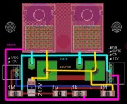
could someone please check the pcb before is send it to oshpark? a short side note: the DRAIN pins will be removed, as the heatsink is connected to DRAIN and this is where the wire will be soldered to. and so there is enough space for a big 4mm2 solid copper wire connecting SOURCE pins (this is what the two holes are for)
while redesigning the pcb i realized that the 3b version does not need a toggling switch at all?! while the switch is open GATE gets pulled down to GND actively. but will the 1M resistor not drain the battery all the time?. not that it's much but still ...
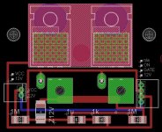

Can you post a schematic? There's a couple things I'm not getting.
The labels on the right side connector appear to be swapped. It seems like there should be a source connection to the switch somewhere I don't see.
The labels on the right side connector appear to be swapped. It seems like there should be a source connection to the switch somewhere I don't see.
izeman
1 GW
fechter said:Can you post a schematic? There's a couple things I'm not getting.
The labels on the right side connector appear to be swapped. It seems like there should be a source connection to the switch somewhere I don't see.
i copied your 3b schematic into eagle. then arranged all parts.
you are correct, ON and GATE are swapped.
source is connected to the two big green squares.

izeman
1 GW
Similar threads
- Replies
- 8
- Views
- 1,038
- Replies
- 9
- Views
- 1,907
- Replies
- 25
- Views
- 2,892
- Replies
- 5
- Views
- 3,303


