izeman
1 GW
of coursefechter said:The other resistor, the 1M one. Try 2M. This will slow it down by 2x.
of coursefechter said:The other resistor, the 1M one. Try 2M. This will slow it down by 2x.


i tested several fets. and they all show the same. i will build the whole thing with one new FET now to try again.madin88 said:strange thing. maybe it could be even though the measurements are ok one FET has a failure..
do you see still voltage at the output if you pull down the gate to GND?
I noticed that. If I just added ground wires to end and src and no other part, touching the gate with my finger made the fet switch.fechter said:FET gates are extremely sensitive and can build up enough charge to turn on with picoampres of current. Just humidity could do that.
madin88 said:if you put in gate to source resistor equal to R1, than the zener sees only half the battery voltage right?
example if 40V battery only 20V on the zener.
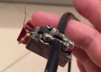
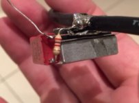
Thats a cool pack for a battery. I was using a small precharge resistor across the operating relay which should suppress the inrush current and thus protecting the capacitors.Gregory said:Hi,
I had a play around and made the Jeremy Harris FET based inrush protection switch.
It took me a whole day but I was stoked when it worked.
First time I’ve made a PCB since I was 15yo.
The bike is 15s lipo that peaks at 30A 1600W.
I made mine flat, soldering the FETs to the PCB trace. I used 3 x IRFB4110’s and they don’t get warm (on my short trips which are limited by the 5Ah pack on this bike, must try it with a bigger Ah).
I notched the powerpole housings so they sat flat.
Connectors are mirrored so you can’t really plug battery into controller socket on the board.
View attachment 3
View attachment 2
And a minor change was made to put a set of charge plugs next to the switch to make recharging much easier. And this is the final product.
View attachment 1
And it slid into the small tool bag on my bike.
In hindsight I should have gotten a finer pen for the etch resist. Next plan is to learn to use one of the software packaged like KiCAD.
I might relocate the switch.
And if doing another one I would place the powerpole housings on top of the PCB rather than in line with it.
Thanks for the schematic Jeremy.
Greg
I like it.fechter said:You could try using the switch to short the gate to source and leave the 1M resistor always on. When the switch is on (gates shorted) the output will be off but the 1M resistor will drain 1uA per volt on standby. This is a very small amount of drain and would be OK for years.

Ya - exactly right.Alan B said:This will quickly open the FETs, but the capacitance in the controller will still take a long time to drain out, so the CA may still complain.
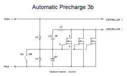
what about the 1M resistor between gate and source?teklektik said:I've taken the liberty to update the original draft as 3b
