• Howdy! we're looking for donations to finish custom knowledgebase software for this forum. Please see our Funding drive thread

Adaptto Mini-E/Max-E Owner's Thread

Cool. I'm running 20S as well and have a 30A coil to tuck up in the neck of the alpha. I'm happy with 20A charging current, even 15A would be OK if needs be. I already have the neutrik non-waterproof cover to keep out bulk mud and stuff but if it doesn't fit I'll hunt for something else.

Damn those 8 pin plugs are expensive! Any cheap sources ? I'm looking at $30 per side which is a bit rude...
 
This last round, I purchased my 8 pin connectors from Zack Electronics in California (for a bit less than $30) but shipping may add a bundle to get it around the world.
 
wow this 8P metal connector is really gold stuff...


but....

i will take a call with them....because the NL4FX has same tec specs. its just "plastic" yes.
and it get really hot.
but those connectors are for "build in" housing so...if it is 80-90° inside, it feels not "right"
but who cares when all stuff is build for it, wires up to 200°, heatshrink 140°

and on that place where it is installed i have no batteries.
i will report back what they will tell me about that rating of 40A and the heat generated on 35A.

8 times higher price with same tec specs is a call worth :p
 
iam on the way to install the thermistor delivered with the Max-E.

as i found in this and other threads,
just pin the thermistor to your windings or stator,
solder one end to the adaptto PIN4 and the other end to the hall negativ.


but i found also some interesting stuff from our well known user tekle....

teklektik said:
In the ideal situation, the temp sensor in the motor would be connected to the two pins of the CA temp sensor and to nothing else. This gives the best signal and the most accurate readings.

Unfortunately, that requires pulling an extra wire through the axle, so the motor folks generally just tie the sensor Gnd to the hall Gnd inside the motor and route out only the signal wire. This works because the CA Gnd is tied to the controller Gnd by means of the CA-DP connector. The CA sensor input is relative to the CA Gnd (one of the two sensor connector pins) and so by a long circuitous route (pun intended), the CA sensor Gnd goes through the CA, down the CA-DP cable, into the controller to controller Gnd, then out the hall wiring to the motor where it finally meets the sensor Gnd pin (whew...)

Sharing Gnd with the halls works okay, but isn't the best means to handle a small analog signal. If you run a headlamp or something that draws a lot of power from the CA Aux power port, then there is a small voltage impressed across the Gnd wire in the CA-DP cable by the accessory current. This small voltage shift therefore appears in the circuit for the temp sensor and throws the apparent sensor voltage off a bit. This small error isn't really a big deal since the CA temp limits are just guesstimates of what's 'safe' anyway.

There are different schools of thought on running the CA sensor Gnd connection directly to the hall Gnd connection (second wire), but I prefer not to do so to minimize stray current running in and out of analog sensor pins on the CA - since any current looking for a route to controller GND (like that headlamp) would head out that way as a second parallel path to that described above. That said, doing so isn't going to damage anything electrically, but since it offers no material advantage, there seems no good reason to do it - just rely on the single CA Gnd to route power off the CA PCB as the designer intended.


so now iam not sure if iam on the right way?!
 
Using the Hall negative is absolutely okay.
I am using this Connection too and i have absolutely no Problems.


I recently bought an Max-e and it nearly works perfect!
There are only 2 issues that i don´t understand.
I am using an QS205 Motor with an MAX-E. When i start an Autodetect process the Controller always detects an Hall angle of 180*.
The Autodetect process finishes without Problems and i can ride my bike with the settings from Autodetect but the acceleration is very slow, even under boost mode.
Do i have to swap two Hall Sensor Signal wires or something to get the right Angle?

The other Problem is that i am using the BMS with an 20S Lipo Battery. The first 16 cells are getting identified without Problems. The fifth BMS Board is connected with the fourth Board via the three Solderpads on the top side of the Boards.
What do i have to Change in the BMS settings so that the fifth Board gets recognized ?
 
Hello Hexa,

Do i have to swap two Hall Sensor Signal wires or something to get the right Angle?

Normally, this should not be the case. 180° hall angle is perfectly fine. Do you have tried different timing settings? What currents and temperatures are you reading from your motor?

What do i have to Change in the BMS settings so that the fifth Board gets recognized ?

Wire it like this. Make sure you scrape off all the solder stop paint before soldering to the pads.
BMS-20s.JPG


Go to Options/BMS Setup/Channel A config and set it up like this:
BMS-Setting.JPG


This should be enough.
 
Now I need your help.

I brought a used Mini-E for my girlfriend's bike from a forum member. It arrived but unfortunately does not work and I cannot return it.

When I connect the display to the controller and hook it up to my power supply it does not turn on and the display stays black. As it is likely to have no warranty, I will try and fix it myself if I am able to.

So dear adaptto geeks, please give me a tip what can cause the controller not to start.

Things I measured:
1) Opened the display and measured all three wires vs. ground: each 0V. so no voltage gets to the display.
2) Opened the controller and measured all three wires vs. ground at the pcb connection where the cable to the display is attached. Again 0V. so no voltage gets to the connectors on the pcb :shock:
3) The controller has ON/OFF functionality, so I measured the voltage beween both wires when they are not connected. The result is the voltage of my power supply which I set between 60 and 80v. If I connect both wires there is a spark, which is the same for my working controller, so I think this is the right reaction.
4) Measured the continuity of all of the ribbon cable wires as this was the most likely thing to get damaged by the transport. But they are all fine.

The PCB looks good, too. So do all the capacitors. There are visually no black spots or disconnected routes on the pcb. The previous owner must have replaced R113 as you can see soldering flux around it. But the resistor is okay. R33 also lookes a bit like someone changed it, too. It says "123" on top and has the related 12kOhm, though.

bottompcb.JPG

upsidepcb.JPG


Is there something like a fuse for the internal logic of the controller? It seems that the hole logic is suspended or the step down converter to 5v is damaged. Shall I connect external 5V to the 5V connector? I'm a bit worried about this, to be honest.
What happens if the controller was connected to + and - in reverse? What is the most likely component to die?

Any hint where to start my error search or where to find more Information about the schematic is highly appreciated! If you need more information, please let me know. I even have an oscilloscope here, if this helps.
 
Handy1609 said:
Now I need your help.

I brought a used Mini-E for my girlfriend's bike from a forum member. It arrived but unfortunately does not work and I cannot return it.

When I connect the display to the controller and hook it up to my power supply it does not turn on and the display stays black. As it is likely to have no warranty, I will try and fix it myself if I am able to.

So dear adaptto geeks, please give me a tip what can cause the controller not to start.

Things I measured:
1) Opened the display and measured all three wires vs. ground: each 0V. so no voltage gets to the display.
2) Opened the controller and measured all three wires vs. ground at the pcb connection where the cable to the display is attached. Again 0V. so no voltage gets to the connectors on the pcb :shock:
3) The controller has ON/OFF functionality, so I measured the voltage beween both wires when they are not connected. The result is the voltage of my power supply which I set between 60 and 80v. If I connect both wires there is a spark, which is the same for my working controller, so I think this is the right reaction.
4) Measured the continuity of all of the ribbon cable wires as this was the most likely thing to get damaged by the transport. But they are all fine.

The PCB looks good, too. So do all the capacitors. There are visually no black spots or disconnected routes on the pcb. The previous owner must have replaced R113 as you can see soldering flux around it. But the resistor is okay. R33 also lookes a bit like someone changed it, too. It says "123" on top and has the related 12kOhm, though.

bottompcb.JPG

upsidepcb.JPG


Is there something like a fuse for the internal logic of the controller? It seems that the hole logic is suspended or the step down converter to 5v is damaged. Shall I connect external 5V to the 5V connector? I'm a bit worried about this, to be honest.
What happens if the controller was connected to + and - in reverse? What is the most likely component to die?

Any hint where to start my error search or where to find more Information about the schematic is highly appreciated! If you need more information, please let me know. I even have an oscilloscope here, if this helps.

I had a very similar problem as yours, my display wouldn't turn on. It turned out the on/off cable was shorted.
 
Can anyone help with this...

My charge screen always shows 100% when charging and therefore there is no estimation of charging time.
I am wondering too if this stops or alters the charging sequence from going into CV mode as the battery reaches its end sequence of charging.
I think it happens once the controller has been turned off after a ride.
Does anyone know how to get around this?
 
brumbrum said:
Can anyone help with this...

My charge screen always shows 100% when charging and therefore there is no estimation of charging time.
I am wondering too if this stops or alters the charging sequence from going into CV mode as the battery reaches its end sequence of charging.
I think it happens once the controller has been turned off after a ride.
Does anyone know how to get around this?

Have you set all Settings in the "charge Settings" right?

Today i got an Error at Charging too!
My Max-e charged my 20S Lipo Battery with an 12V 500W PSU at 30A. Until 81V the charging process worked great.
As i looked after the Bike some time later i noticed that the Controller was in Protect and the display showed "no Charging Voltage detected".
After disconnecting the charging coil i noticed that one phase was shorted!
It was the one where i had connected the coil!
One FET of the Phase was defective an the Driver board was broken too!

What went wrong there?
Had anyone else a problem like that ?
 
Question if anyone can help.

I've been doing lots of wheelies lately and can get the bike to start a wheelie as high as 30MPH / 48 KPH if my voltage is higher in the 80's.

When the voltage drops to mid 70's and lower my bike lacks the power to get the front up at 30 MPH. I am surprised that such a few volts will make a big difference in power. I wonder if it could also be partly because of motor temps.

My question is what controller settings would best help to get more power when my voltage drops into the mid 70's and lower?

Should I increase PWR, battery amps, or phase amps? I would have to unlock the controller to get more phase amps but would consider it.

Thanks.
 
thats the price of your GA cells.
they drop 12v if you are on 150a.
from full 20s they drop to 72v (here is no voltage cut off)

but when you are on 75 resting voltage they "want" to drop below your lvc and controller reduces power.
so from a half full pack you are on half "power".

so we have here not "such few volts"....just the limit of your GA cells.

if you dont care about LVC and "watch" your cells/voltage, just set LVC to 50v
controller will not reduce power now.
 
Hexa said:
brumbrum said:
Can anyone help with this...

My charge screen always shows 100% when charging and therefore there is no estimation of charging time.
I am wondering too if this stops or alters the charging sequence from going into CV mode as the battery reaches its end sequence of charging.
I think it happens once the controller has been turned off after a ride.
Does anyone know how to get around this?

Have you set all Settings in the "charge Settings" right?

Today i got an Error at Charging too!
My Max-e charged my 20S Lipo Battery with an 12V 500W PSU at 30A. Until 81V the charging process worked great.
As i looked after the Bike some time later i noticed that the Controller was in Protect and the display showed "no Charging Voltage detected".
After disconnecting the charging coil i noticed that one phase was shorted!
It was the one where i had connected the coil!
One FET of the Phase was defective an the Driver board was broken too!

What went wrong there?
Had anyone else a problem like that ?


wow that is hard. what firmware did you use?
no warranty? in this thread theres no other one where it happend. but beside that, (iam not that technical expert) supply voltage has to be 24v or above for using the coil.
maybe the gap from 12v to 84v is too much?!
 
I have the same problem. My Max E always show "until 100% 0min, 0sec."

I would like to be able to use this nice gadget to know how long it takes until I can drive my bike again without having to calculate that.. :/
 
BCTECH said:
Handy1609 said:
Now I need your help.

I brought a used Mini-E for my girlfriend's bike from a forum member. It arrived but unfortunately does not work and I cannot return it.

When I connect the display to the controller and hook it up to my power supply it does not turn on and the display stays black. As it is likely to have no warranty, I will try and fix it myself if I am able to.

So dear adaptto geeks, please give me a tip what can cause the controller not to start.

Things I measured:
1) Opened the display and measured all three wires vs. ground: each 0V. so no voltage gets to the display.
2) Opened the controller and measured all three wires vs. ground at the pcb connection where the cable to the display is attached. Again 0V. so no voltage gets to the connectors on the pcb :shock:
3) The controller has ON/OFF functionality, so I measured the voltage beween both wires when they are not connected. The result is the voltage of my power supply which I set between 60 and 80v. If I connect both wires there is a spark, which is the same for my working controller, so I think this is the right reaction.
4) Measured the continuity of all of the ribbon cable wires as this was the most likely thing to get damaged by the transport. But they are all fine.

The PCB looks good, too. So do all the capacitors. There are visually no black spots or disconnected routes on the pcb. The previous owner must have replaced R113 as you can see soldering flux around it. But the resistor is okay. R33 also lookes a bit like someone changed it, too. It says "123" on top and has the related 12kOhm, though.

bottompcb.JPG

upsidepcb.JPG


Is there something like a fuse for the internal logic of the controller? It seems that the hole logic is suspended or the step down converter to 5v is damaged. Shall I connect external 5V to the 5V connector? I'm a bit worried about this, to be honest.
What happens if the controller was connected to + and - in reverse? What is the most likely component to die?

Any hint where to start my error search or where to find more Information about the schematic is highly appreciated! If you need more information, please let me know. I even have an oscilloscope here, if this helps.
I had a very similar problem as yours, my display wouldn't turn on. It turned out the on/off cable was shorted.

Mine Also failed to Launch on first connection, advice from Adaptto was "The problem lied in extention of On/Off wires which you've soldered. The cables inside the isolation of your extention are most likely distorted - this prevented controller from operation. Since extention of wires was made by you and on your own risk - this repair have to be paid as well as return shipment should be covered."
Hmmm, I soldered small connectors on the end and put them in a plastic connector block, spliced and soldered extensions to the small wires coming out of the Max-E then folded them back on themselves and taped them to avoid putting strain on them. Supposedly, something I did in this process "distorted" them and caused the problem which has cost me about $180 USD in freight and repairs and put my Flux Alpha build back by about six weeks. I thank Adaptto for fixing it promptly and cheaply, BUT, now with someone else having the same issue, I wonder if there is some fault in fabrication that makes these wires very susceptible to damage under normal use (ie extending the wires etc). If that's the case that little bit of the design might need a re-think.
 
Does anyone have a stonkin Adaptto setup for a MXUS 3k Turbo motor that they would care to share? I tried to look back through this thread a few weeks, but I only got back 3 pages coz I keep getting side-tracked with other interesting stuff, and using the search isnt much better, its even more distracting!
 
SUNDRIVE said:
Does anyone have a stonkin Adaptto setup for a MXUS 3k Turbo motor that they would care to share? I tried to look back through this thread a few weeks, but I only got back 3 pages coz I keep getting side-tracked with other interesting stuff, and using the search isnt much better, its even more distracting!


I think Merlin runs a mxus and adaptto?. Maybe try pm'ing him? Also forum member Morati.

I have just ordered one for a spare motor, but feel it may overheat easily compared to my cromotor when off-roading in hilly areas.
 
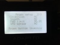
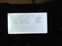
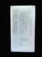
Guys, i am running a wuxxing thumb throttle for variable regen. It works well but would like to increase the breaking force applied. How do i do this?
 
Here are the settings. The regen works well, would just be nicer if i had a bit more stopping power.
 

Attachments

  • image.jpeg
    image.jpeg
    38.5 KB · Views: 3,059
  • image.jpeg
    image.jpeg
    34.4 KB · Views: 3,059
  • image.jpeg
    image.jpeg
    31.2 KB · Views: 3,059
Quokka said:
Guys, i am running a wuxxing thumb throttle for variable regen. It works well but would like to increase the breaking force applied. How do i do this?

Done the thumb throttle brake calibration thing, adjusting upper and lower limits etc? I have a RH Wuxing mounted awkwardly, upside down I think, or backwards, on the LH bar and it works very nicely as a regen brake with Adaptto Mini-E and MXUS motor. Dont know if Wuxing make a LH thumby, in the smaller, more compact type of the two styles I have seen, I'd like to know if they do coz ours is a little bit cack-handed !
 
ActiveMode
+
Force Active

if you setup these to "on" your ebrake will be stronger.
it is explained in the manual.

i orefer both modes off because the regen is alot stronger on higher speeds.
i take the regen brake to slow down on higher speeds.

if you set these to on, the brake at lower speeds is stronger (but you will hear also a "click" when it goes in active mode)

also set your rated current as high as your battery can and in your Power Mode PRofiles "screen"

IPRA ...set this to highest possible (385) it is the phase amps used for braking.

i have also torque rise to the maxium set.

let me know if this works for you.


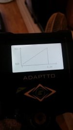
can you do me a favor also?

make a photo of your throttle "range"?
 

Attachments

  • 2016-07-27 13.55.38.jpg
    2016-07-27 13.55.38.jpg
    13.6 KB · Views: 3,043
Quokka said:
Here are the settings. The regen works well, would just be nicer if i had a bit more stopping power.

Will you be able make a complete stop only using the regen?
I think I have some bleeding problem on my disc break and only using regen brake for now. high speed is ok, but so far it can't make the bike stops completely at traffic lights.
I assume if the controller can lock up the wheel( for anti thief), then it should have enough power to make a dead stop of the bike?!
 
Back
Top