
You are using an out of date browser. It may not display this or other websites correctly.
You should upgrade or use an alternative browser.
You should upgrade or use an alternative browser.
Adaptto Mini-E/Max-E Owner's Thread
- Thread starter GCinDC
- Start date
Price mainly, but also, it's generally not needed for the lighter Fighter. I want my fighter to push the boundaries of performance in a light small package.Artur said:Why not just to buy Max-e?? :wink:
")
That and I'm already doing mods like that to my motor:
http://endless-sphere.com/forums/viewtopic.php?f=30&t=56965&start=100#p1009434

One of the other reasons is I might be running 18S, not the 12S I currently run. If I do, I will need to run another 3 fans somewhere so I can still run them directly off the battery in series...the controller seems like the most logical place considering the motor will be capable of much more power.
Cheers
ridethelightning
1 MW
- Joined
- Jul 21, 2013
- Messages
- 2,010
should be interesting.
iv noticed my mini-e overheats much faster than my max-e. even at around 3-4kw cont., on a warm day(25C or so )
id also be considering putting finned heatsink, preferably copper, on the side where the fets are. others have done this and reported great improvement.
youll need good cool airflow past the fins. im not so sure if air through the controller would have much better effect than this. would be good to ask adaptto to find out which parts are prone to overheat, but its got to be the fets mainly id say, as they are dealing with the high current.
even if unlocked, surely the controller will limit power as its fets rise towards critical temps, typically 70C.
Some good points guys. I need to use these fans somewhere...maybe external heatsinks + the fans on them would work better?
What's the best way to attach the heatsinks? Thermal Epoxy?
What's the best way to attach the heatsinks? Thermal Epoxy?
Cowardlyduck said:Some good points guys. I need to use these fans somewhere...maybe external heatsinks + the fans on them would work better?
What's the best way to attach the heatsinks? Thermal Epoxy?
Thermal pad: http://www.ebay.com/itm/190851585061
Ummm...maybe not. I've already got some of that and it's not very strong. I seriously doubt it would hold a heatsink to the side of a controller bouncing up and down under the bike.striker54 said:Thermal pad: http://www.ebay.com/itm/190851585061
I'm thinking some thermal paste + bolts is probably the best way to go, but if not that, thermal epoxy would be better than the pads.
Cheers
Remove the screws from the side of the case, these hold the internal heatsink / fets to the inside of the controller case, then drill holes in your heatsink, put heatsink paste or pads between the controller case and the heatsink. Go to a shop that sells screws / fastners and buy some slightly longer screws, that will go through the external heatsink and into the internal one, you can then screw the heatsink to the case using the existing screws. This is basically what I am doing with mine to keep it cool, I also have it clamped to the inside of my aluminium battery box with a heat transfer pad in between the controller and the box, to use the battery box as a heatsink. The external heatsink im adding is just to add even more cooling, as im going to add a fan to suck air into the battery box and over the heatsink, then out a vent in the top.

madin88 said:thermal paste normally has better heat transfer than pads so use this.
Not true: http://www.candlepowerforums.com/vb...-Myth-Busted-Thermal-Paste-Beats-Thermal-Tape
Allex
100 MW
I would not take that post as a scientific result Thermal paste is preferred when you need to cover small differences between metal. If you use to much it will instead isolate rather then have a good transfer, just like a thermal pad do. When you have a bigger gap or need some flex, like on laptops, thermal pads are used. No serious overclocker uses thermal pads when overclocking simply because paste is superior when you need to close a very small air gaps.
Before you apply your heatsink, make sure to "lap" the controller case and heatsink, see GCinDC thread.
Thermal paste is preferred when you need to cover small differences between metal. If you use to much it will instead isolate rather then have a good transfer, just like a thermal pad do. When you have a bigger gap or need some flex, like on laptops, thermal pads are used. No serious overclocker uses thermal pads when overclocking simply because paste is superior when you need to close a very small air gaps.Before you apply your heatsink, make sure to "lap" the controller case and heatsink, see GCinDC thread.
That's good to know about the screws. I will definitely do that in that case.
Thermal padding is known to be less effective in the PC overclocking world...I wonder if there is something different about torches heat generation?
How have others mounted the controller to their frames? I already have some holes under mine from the existing Infineon controller. I should be able to reuse at least one of these, but does the Adaptto controller come with any kind of mounting plate?
Also, when I mount it, I will put some thermal padding (not paste) between the frame and the controller for added thermal transfer and vibration dampening.
Cheers
Allex
100 MW
Check my build thread on how I did to mount the controller without ruining the stock frame.
Guys, good news regarding motor cut outs on my bike!
in my case its a completely different "problem". the controller cuts out because battery sags to lvc and NOT because it went in protection.
yeah, no need to solder a resistor onto another on the board btw: Adaptto told me maximum 6 controllers had been shipped with this problem..
Some may call me stupid now, but its still very strange because sometimes it works smooth and another time it cuts and resumes power very jerky. thats what i meant by non-reproducible because its not always the same.
after increasing vsoftlimit to 3V it was better, but sometimes acceleration still can be jerky.
Any ideas why it does not act always the same?
in my case its a completely different "problem". the controller cuts out because battery sags to lvc and NOT because it went in protection.
yeah, no need to solder a resistor onto another on the board
btw: Adaptto told me maximum 6 controllers had been shipped with this problem..Some may call me stupid now, but its still very strange because sometimes it works smooth and another time it cuts and resumes power very jerky. thats what i meant by non-reproducible because its not always the same.
after increasing vsoftlimit to 3V it was better, but sometimes acceleration still can be jerky.
Any ideas why it does not act always the same?
That is really strange . my controller needs soldering extra resistor. i'm pretty sure its no voltage sag problem at mine.What i don't understand is that there are not many people with these problems. I measured that there is a 8,3kohm resistor on my controller. No i have to put another 30kohm resistor over the old one. Someone can explane what this little resistor do and what the effect is of soldering another parallel over it.
ElectroRider
1 W
madin88 said:Guys, good news regarding motor cut outs on my bike!
in my case its a completely different "problem". the controller cuts out because battery sags to lvc and NOT because it went in protection.
Any ideas why it does not act always the same?
Hey, I had a similar issue but solved it when I got a new set of batteries, but what I did notice with the old batteries was that the colder it was the greater the voltage sag, maybe the cut outs are worse for you on slightly colder days.
ElectroRider
ElectroRider said:Hey, I had a similar issue but solved it when I got a new set of batteries, but what I did notice with the old batteries was that the colder it was the greater the voltage sag, maybe the cut outs are worse for you on slightly colder days.
ElectroRider
yes it was very cold. the battery temperature was only a few degree C over zero. below 40% SOC voltage starts to drop to LVC (3,2V / cell) at 7-8kW.
Adaptto E-Drives Lab
100 W
Dear Friends,
We've received many questions recently regarding the external on/off button (or a key switch) implementation for our controller.
Firstly, for those ordering the controllers now - we can include this option upon request.
Secondly, if you already got the controller - you could always send it to us and we will install the cable for button integration at reasonable price (no more than 20 USD). Return shipping is always on us.
Thirdly, if you got the controller and are not ready to wait for the shipping period we have worked out the following simple guide on how to do it yourself.
PLEASE NOTE: use the guide ONLY if you've got enough experience in soldering because opening up the controller automatically stops the warranty coverage. Thus Adaptto E-Drive Lab Ltd. will not be liable for any problems caused by your actions starting from the controller opening.
Let's start:
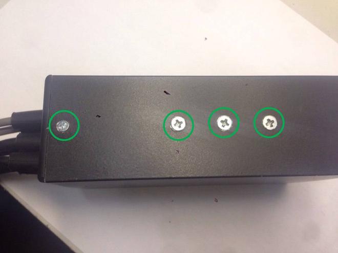
1) To open up the controller - GENTLY undo the following screws
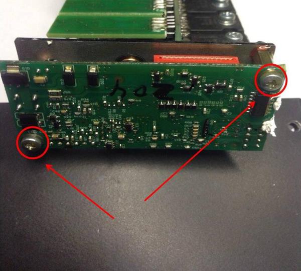
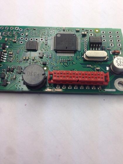
2) Withdraw the inner part of the controller and unscrew these studs thus releasing the processor board:
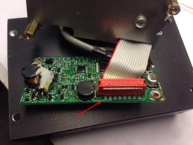
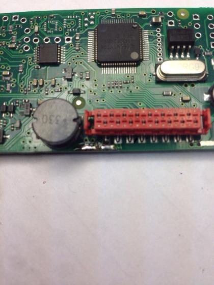
3) On processor board you need to concentrate on the line shown:
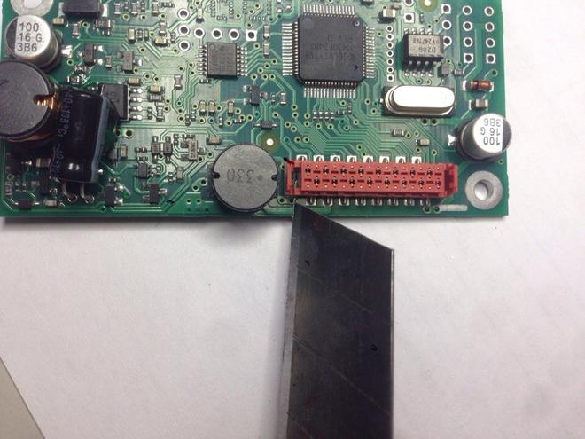
4) ACCURATELY cut the line in the middle (with the knife for example)
Result:
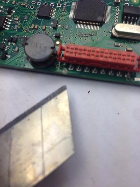
5) Clear the rest of the line up until the copper:
6) Tin-plate:
7) Solder the wire for the button (DON'T forget to apply the thermal setting) :
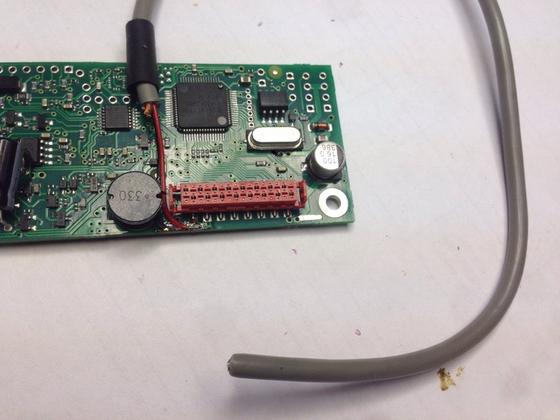
8 ) That's it. Now just drill out the new bore for the cable soldered. Here is the perfect place for it:
Hope this helps,
All the best!
We've received many questions recently regarding the external on/off button (or a key switch) implementation for our controller.
Firstly, for those ordering the controllers now - we can include this option upon request.
Secondly, if you already got the controller - you could always send it to us and we will install the cable for button integration at reasonable price (no more than 20 USD). Return shipping is always on us.
Thirdly, if you got the controller and are not ready to wait for the shipping period we have worked out the following simple guide on how to do it yourself.
PLEASE NOTE: use the guide ONLY if you've got enough experience in soldering because opening up the controller automatically stops the warranty coverage. Thus Adaptto E-Drive Lab Ltd. will not be liable for any problems caused by your actions starting from the controller opening.
Let's start:
1) To open up the controller - GENTLY undo the following screws
2) Withdraw the inner part of the controller and unscrew these studs thus releasing the processor board:
3) On processor board you need to concentrate on the line shown:
4) ACCURATELY cut the line in the middle (with the knife for example)
Result:
5) Clear the rest of the line up until the copper:
6) Tin-plate:
7) Solder the wire for the button (DON'T forget to apply the thermal setting) :
8 ) That's it. Now just drill out the new bore for the cable soldered. Here is the perfect place for it:
Hope this helps,
All the best!
lennovich said:What do you mean with apply the thermal setting?
I think he means that you should use a soldering iron at a fixed temperature, that is not too hot, so you don't need to be as concerned about affecting nearby components.
Seven
10 W
Adaptto, could you tell us the difference between the ON/OFF modification you describe here and the method of cutting the red wire in the display cable, is there an advantage to using one method over an other?
Thanks
Thanks
ridethelightning
1 MW
- Joined
- Jul 21, 2013
- Messages
- 2,010
+1Seven said:Adaptto, could you tell us the difference between the ON/OFF modification you describe here and the method of cutting the red wire in the display cable, is there an advantage to using one method over an other?
Thanks
exactly my thoughts....
GreenRoad
100 W
ridethelightning said:+1Seven said:Adaptto, could you tell us the difference between the ON/OFF modification you describe here and the method of cutting the red wire in the display cable, is there an advantage to using one method over an other?
Thanks
exactly my thoughts....
I talked / asked adaptto also for that solution - "hack"
The differenze to the switch of - over the display - is the usage of power.
It should be the same if you disconnected the the battery.
For people - who do not use an Main / Fuse Switch - this is an good solution.
I will use the switch over the controller - "hack" to mount an RFID Switch.
Seven
10 W
Has anyone taken a current draw reading on the screen switch vs the controller switch
Similar threads
- Replies
- 3
- Views
- 1,970
- Replies
- 98
- Views
- 22,827
- Replies
- 9
- Views
- 4,226