
You are using an out of date browser. It may not display this or other websites correctly.
You should upgrade or use an alternative browser.
You should upgrade or use an alternative browser.
Adaptto Mini-E/Max-E Owner's Thread
- Thread starter GCinDC
- Start date
Doctorbass said:20s on a kv of 12 is ok too but you will not be able to use the full phase amp without any worrie....
i'm going to set up such combination. in detail: 20s12p 25R, MXUS 3000 3T
as my Max-E already is about 20 month "old" (and i believe no warranty anymore) i yesterday made it ready for unlocked firmware
with ready i mean:
all 8mm² wires
additional ceramic caps
better + additional electrolytic caps with more ripple current and µF
will post some pics later or in new thread. now the glue around the caps must hardening.. wish me luck that it still works
")
ridethelightning
1 MW
- Joined
- Jul 21, 2013
- Messages
- 2,010
madin88 said:Doctorbass said:20s on a kv of 12 is ok too but you will not be able to use the full phase amp without any worrie....
i'm going to set up such combination. in detail: 20s12p 25R, MXUS 3000 3T
as my Max-E already is about 20 month "old" (and i believe no warranty anymore) i yesterday made it ready for unlocked firmware
with ready i mean:
all 8mm² wires
additional ceramic caps
better + additional electrolytic caps with more ripple current and µF
will post some pics later or in new thread. now the glue around the caps must hardening.. wish me luck that it still works
very daring to upgrade such a nice toy.
hope it works for you again.
any info re. components you use would be great
Doctorbass
100 GW
madin88 said:Doctorbass said:20s on a kv of 12 is ok too but you will not be able to use the full phase amp without any worrie....
i'm going to set up such combination. in detail: 20s12p 25R, MXUS 3000 3T
as my Max-E already is about 20 month "old" (and i believe no warranty anymore) i yesterday made it ready for unlocked firmware
with ready i mean:
all 8mm² wires
additional ceramic caps
better + additional electrolytic caps with more ripple current and µF
will post some pics later or in new thread. now the glue around the caps must hardening.. wish me luck that it still works
That's interesting! witch ceramic caps value do you use?
I also tought ading some and getting the 10AWG wires to be upgraded... I also have a great Philips 100V 15000uf Cap here with only 5miliohm ESR... that i could paralel to teh controller input. i think it have 26A ripple current
Doc
GreenRoad
100 W
Doctorbass said:madin88 said:Doctorbass said:20s on a kv of 12 is ok too but you will not be able to use the full phase amp without any worrie....
i'm going to set up such combination. in detail: 20s12p 25R, MXUS 3000 3T
as my Max-E already is about 20 month "old" (and i believe no warranty anymore) i yesterday made it ready for unlocked firmware
with ready i mean:
all 8mm² wires
additional ceramic caps
better + additional electrolytic caps with more ripple current and µF
will post some pics later or in new thread. now the glue around the caps must hardening.. wish me luck that it still works
That's interesting! witch ceramic caps value do you use?
I also tought ading some and getting the 10AWG wires to be upgraded... I also have a great Philips 100V 15000uf Cap here with only 5miliohm ESR... that i could paralel to teh controller input. i think it have 26A ripple current
Doc
to place a higher capacity is not always a good solution.
Its better to optimize the wires from the battery to the controller.
or use high quality cells
My measure show me - that the battery current is always taken out of the battery (the current on the display)
I could not measure the phase current - outside the controller - that means it comes from the controller cap bank.
- in relation to kelly - there i also could measure the phase current - in the battery line.
a higher capacity could stress the controller / battery - you should know what you are doing and not trying....
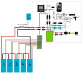
well its time for action. my batteries have arrived and I finally have my battery and all other bits to complete my build. Just wanted to put up my final connections and make sure I've had this looked over by people with experience.
when connecting my battery bms does it matter which battery goes to what balance input? The battery is fine to be in series but connecting the balance leads individually like this right? wasnt sure if I had to do the balance leads different if my battery packs were in series.

when connecting my battery bms does it matter which battery goes to what balance input? The battery is fine to be in series but connecting the balance leads individually like this right? wasnt sure if I had to do the balance leads different if my battery packs were in series.
Attachments
Doctorbass
100 GW
GreenRoad said:to place a higher capacity is not always a good solution.
Its better to optimize the wires from the battery to the controller.
or use high quality cells
My measure show me - that the battery current is always taken out of the battery (the current on the display)
I could not measure the phase current - outside the controller - that means it comes from the controller cap bank.
- in relation to kelly - there i also could measure the phase current - in the battery line.
a higher capacity could stress the controller / battery - you should know what you are doing and not trying....
Good to know.. I always thought that the cap would be important at the controller input..
On my Max-E I have about 2 foot of industrial quality gauge 6 and Xt150 connectors and SB50 Anderson and I'm using top quality Farasis cels same as in the Zero. The internal resistance of each cells is about 1.2 milliohm and I have 22 in serie. the Ri seen by the adaptto is about 60miliohm.
I will remove one of the bus caps inside the Max controller to measure his RI.. and if needed I will replace all with low ESR one. I have few left form my 36 fets controller project.
What uF and voltage value of smaller ceramic cap do you use? and how many do you install on the DC bus ?
Doc
GreenRoad
100 W
Hello Doc
its not so easy.... we can discuss this at an extra thread.....
it also depands on the controller - sinus /trap - signalform.
The main thing is the right setup - you need physicaly the way to transport the energy.
Thats why good cells / high capacity are so important. If you current is to high - the cell voltage broke down - or you did not get the high current.
The caps are only an buffer for energy - if the are give energy away - they need at the next moment also energy again - or in other words - the battery gets under load.
The best way is to keep the energy wire as short as possible and use the maximum of possible diameter to reduce the resitance.
The combination of caps / battery should stay in an stable / balanced level.
Normaly the use of cap at the input of the controller ist only needed that you can measure the current of the controller in an stable condition.
To build up an good controller is the peak of electronic development - and no easy
douglashart
100 W
mini Question: can I run a 5v fan off the usb leads? .
thnx for the help
thnx for the help
macribs
10 MW
- Joined
- Jul 22, 2014
- Messages
- 3,702
I think that the 5v port is according to USB specs. So if you find a fan that will run ok with 5v you multiply the mA and you will see if fan will work.
A unit load is defined as 100 mA in USB 2.0, and 150 mA in USB 3.0. A device may draw a maximum of 5 unit loads (500 mA) from a port in USB 2.0; 6 (900 mA) in USB 3.0.As power is equal to current times voltage, all you have to do is multiply 5V per the current your device is drawing from the port.
I don't know what kind of burst you can draw from the 5v usb outlet but I would not go overboard the USB specs unless Adaptto clearly states otherwise.
douglashart
100 W
thnx mac, the fan draws .65w so im thinking at 5v that would be 130 ma?
GreenRoad
100 W
I also could fine nowhere any information.douglashart said:thnx mac, the fan draws .65w so im thinking at 5v that would be 130 ma?
I think 1A max should be possible - otherwise it makes no sens to charge an smartphone over this port.
But adaptto should confirm this, because i could find no information at the manual - and i think there are some people who like to put also other things on this port - like Frontlight for example....
it would help if you explain what disadvantages a higher capacitance could have in this case?GreenRoad said:to place a higher capacity is not always a good solution.
install large capacitors is recommended by Adaptto if you going to push the controller close at the volatage limits. The caps will smooth out voltage spikes which would damage the FET's.
normally electrolytic caps are for low frequency and ceramic caps for higher freqeuncy spikes.
yes thats right, but at least there are always 30cm or more more total wire / interconnection length from battery to controller and this wire has inductance which causes voltage spikes.Its better to optimize the wires from the battery to the controller.
or use high quality cells
and from what i know in relation to spikes, caps help more than larger wire.
if RMS phase current is higher than battery current, than RMS phase voltage must be be lower. this means the controller works like a step down converter and the motor is the coil. the more inductace a motor has the less stress for the FET's.My measure show me - that the battery current is always taken out of the battery (the current on the display)
I could not measure the phase current - outside the controller - that means it comes from the controller cap bank.
On the Kelly KBSX controller i have i never have seen more than the battery current limit i have set in the programming software on the CA.- in relation to kelly - there i also could measure the phase current - in the battery line.
i guess there is a problem with the software or firmware (i noticed it can be buggy sometimes) and i also read from another member here who has that problem, but you better should ask fany about this
i did what Adaptto has recommendeda higher capacity could stress the controller / battery - you should know what you are doing and not trying....
GreenRoad
100 W
Hello madin88
We talk here - as i told on an high electronic technical level.
To build up an controller is not a easy thing.
i would do the things adaptto told you - thats the best thing.
normaly you use mosfets which can carry the double of the voltage of the battery.
I know controllers which use the 3 time voltage carry of the battery voltage.
The disadvantage is the higer mosfet resistance and lower switching speed.
You could use Caps for two things.
*compare the wire lengh - if you could not carry PEAK Current over the wire. For that you place Caps between Controller / battery.
but you must think for: i one second the cap give you power - in the next moment the need power
For that is the use of low ESR CAPS .... that the inner resistance is low, and they should not get warm.
The other thing is, that if you use Reku - or your settings of the controller are not well - you are getting energy back from the motor.
For that you must anywhere storage the peak Voltage. The battery pack should normaly take this energy away.
If the energy could not go away - perhaps "open Wire" or conection loose to the controller - the voltage could raise and damage the mosfets.
If you are at the higher side of the max controller voltage - for thats its good to use higher caps.
But i thing Adaptto do this as standard at their controller.
I did not get any problems with higher voltage - because i also use an bat voltage of 14S Limn - 58V.
The caps are very important to have an stable voltage for the mesurement of the controller.
But to collect this topic: its not the best way to place an infinity cap between controller and Battery.
Kelly uses at the KBSX48101 7x390µF 63v United Chemi-Con EKZE630ELL391MK25S - with an impedance of 31 mOhm.
Its also good to use more small caps - than an high capacity cap.
... mosfets are 80V / 80A / 8mOhm - for an 60V rated controller.
The lengh of the wire is no problem for induct voltage - your are geting more problems out - on the side to the motor...
(belive me - we made some measurement at EMV labs....)
if Adaptto has recommended - caps than its okay....
if you have question left.... feel free to phone me .... i think you have my number - german is much easier than english - buts its an good exercise....
this are the stock caps:
http://www.elektronik.ropla.eu/en/magazyn/magazyn/?ic=JAM0564
i have replaced three of them with this guys:
https://www.rutronik24.com/product/rubycon/100zlj820m18x40/5259129.html
http://www.rubycon.co.jp/de/catalog/e_pdfs/aluminum/e_zlj.pdf
they have 350µF more, can carry four times the ripple current and have five times higher load life!
one 560µF 15x35,5mm i have installed additional + 7 pcs ceramic caps (four at the input and one at each group of FET's)
it was no hard work to make all fit and soldering is nice on the the copper bus bars. what it needs is plenty of time and and care.
some pics
before:

after:
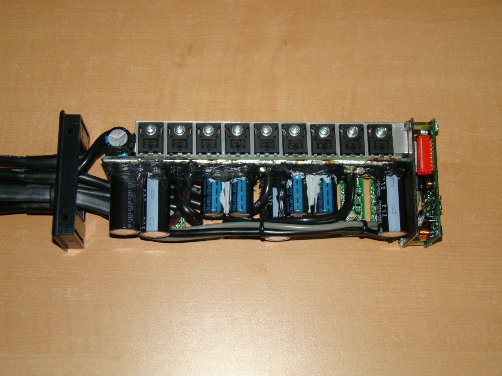


wires:

http://www.elektronik.ropla.eu/en/magazyn/magazyn/?ic=JAM0564
i have replaced three of them with this guys:
https://www.rutronik24.com/product/rubycon/100zlj820m18x40/5259129.html
http://www.rubycon.co.jp/de/catalog/e_pdfs/aluminum/e_zlj.pdf
they have 350µF more, can carry four times the ripple current and have five times higher load life!
one 560µF 15x35,5mm i have installed additional + 7 pcs ceramic caps (four at the input and one at each group of FET's)
it was no hard work to make all fit and soldering is nice on the the copper bus bars. what it needs is plenty of time and and care.
some pics
before:
after:
wires:
skWarDog
100 W
I used Honeywell SS49E hall sensor. I bought 10 of them from China if you, Cowardly Duck or Longshot need one, I can mail it to you? I used a spoke magnet from an old cyclops bike computer, seems to work fine after some tweaking. I have a hydro-mechanical disc brake set-up, so I put it on the cable at the master cylinder. There is a video on Adaptto's website, basically the magnet faces the hall sensor and moves past the gate between pin 2 & pin 3 (pin 1=+5v, pin 2=Grnd, pin 3= output 0v-3v). You don't need a real strong magnet or you will have too big a gap.Stielz said:Hey guys,
Im keen to wire up a linear hall sensor with magnet on the brake leaver for variable regen. Can anyone tell me whats a good magnet - hall sensor combo?
I've no idea what sort of magnet strength range to expect.. Got some small Neodymium magnets I could use if they aren't too strong (outside the range of a linear hall sensor)

Here's a video for lever mounting:
https://www.youtube.com/watch?v=Ym0afjek2LM
Here's another option, Wuxing left side hall throttle. I ordered one, but haven't received it yet. I got the hall sensor dialed in preddy good now, so I'll just throw it in the bin for now.....don't need extra clutter on my bars:
http://www.ebay.com/itm/261590617525?_trksid=p2057872.m2749.l2649&ssPageName=STRK%3AMEBIDX%3AIT
GreenRoad
100 W
good work maddin88
please take care on your copper wire - it could get bad if water comes into the wire - or salt - like in winter - if your are on the road.
If it is possible i never use pure copper wire - if tinned wires are avaiable.....
but its okay ----- only an tip.....
please take care on your copper wire - it could get bad if water comes into the wire - or salt - like in winter - if your are on the road.
If it is possible i never use pure copper wire - if tinned wires are avaiable.....
but its okay ----- only an tip.....
Allex
100 MW
GreenRoad said:I also could fine nowhere any information.douglashart said:thnx mac, the fan draws .65w so im thinking at 5v that would be 130 ma?
I think 1A max should be possible - otherwise it makes no sens to charge an smartphone over this port.
But adaptto should confirm this, because i could find no information at the manual - and i think there are some people who like to put also other things on this port - like Frontlight for example....
Don't use more than 800mAh:
http://endless-sphere.com/forums/viewtopic.php?f=2&t=61183&start=425#p954355
douglashart
100 W
thnx alex ,and thank you for my purchase thru paypal, too easy. the mini came quick and Im happy. the adaptto guys have done all in their power to simplify this unit so even someone like me can work thru it!
Ohbse
10 kW
madin88 said:one 560µF 15x35,5mm i have installed additional + 7 pcs ceramic caps (four at the input and one at each group of FET's)
it was no hard work to make all fit and soldering is nice on the the copper bus bars. what it needs is plenty of time and and care.
That's beautiful work, well done. What's your intended power/usage to justify the upgrades?
Just wanted opinions on this if it is worth it.
Your thoughts about using these 7mm anti spark connectors from hobby king for the main battery connection. They are 7mm which are bigger in size to the xt150 which are 6mm. So they should have at least the same current rating, but with the nice anti spark resistor inside.
http://www.hobbyking.com/hobbyking/store/__42825__7mm_AS150_Anti_Spark_Self_Insulating_Gold_Bullet_Connector_2_Pairs_.html
I know with the way the max-e is setup for charging, you don't have to unplug your main battery that much so sparking is very rare. Because of this is it worth spending the money at around $4.00 a pair for these, or just spark it for the few times you actually disconnect & reconnect the main battery?
BTW. I know you can build your own but I'd just spend the money for a clean job. I also know the other option is a circuit breaker switch, but I don't think I'm going to install one of those, and I would assume those have to spark also inside?
Offroader said:Just wanted opinions on this if it is worth it.
Your thoughts about using these 7mm anti spark connectors from hobby king for the main battery connection. They are 7mm which are bigger in size to the xt150 which are 6mm. So they should have at least the same current rating, but with the nice anti spark resistor inside.
http://www.hobbyking.com/hobbyking/store/__42825__7mm_AS150_Anti_Spark_Self_Insulating_Gold_Bullet_Connector_2_Pairs_.html
I know with the way the max-e is setup for charging, you don't have to unplug your main battery that much so sparking is very rare. Because of this is it worth spending the money at around $4.00 a pair for these, or just spark it for the few times you actually disconnect & reconnect the main battery?
BTW. I know you can build your own but I'd just spend the money for a clean job. I also know the other option is a circuit breaker switch, but I don't think I'm going to install one of those, and I would assume those have to spark also inside?
Madin88 tried these quite a long time ago and they did not work well unfortunately. If theres a quality resistor that could be put in them it would sure be very nice and clean looking. From what I have read precharge should really be used for voltages over 48 volts.
Yes, you are correct a circuit breaker switch will just spark on the inside and the contacts can be ruined over time. However I believe there are some precharging circuit breakers out there.
Similar threads
- Replies
- 3
- Views
- 1,961
- Replies
- 98
- Views
- 22,778
- Replies
- 9
- Views
- 4,211