nukezero
10 kW
Ran into a big problem.
Guys, this case requires a Special BMS. I have not seen a BMS with this. NOw i know what EM3EV means when he says the BMS requires special remote power on.
You see the power on/off switch, usb functions, discharge, and a bunch of other crap goes to the BMS board. There is no other BMS board on the market with these functions. Without it, a lot of features of this case is not going to work. It will not be possible to use the toggle power on/off switch on the outside of the case.
Secondly, sticking a mini BMS isn't going to work. Most of the mini-BMS is only good for 15-20A max. For those of oyu planning to pull 30A like me, this could be a problem.
Lectric-cycles has managed to find a mini-BMS supplier with a 30A draw. But I don't think he will share with us the supplier details, that is fine.
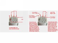
THe only other solution is to not run a BMS and rig the power switch to a automotive relay, so that it will switch on power that way.
Guys, this case requires a Special BMS. I have not seen a BMS with this. NOw i know what EM3EV means when he says the BMS requires special remote power on.
You see the power on/off switch, usb functions, discharge, and a bunch of other crap goes to the BMS board. There is no other BMS board on the market with these functions. Without it, a lot of features of this case is not going to work. It will not be possible to use the toggle power on/off switch on the outside of the case.
Secondly, sticking a mini BMS isn't going to work. Most of the mini-BMS is only good for 15-20A max. For those of oyu planning to pull 30A like me, this could be a problem.
Lectric-cycles has managed to find a mini-BMS supplier with a 30A draw. But I don't think he will share with us the supplier details, that is fine.
THe only other solution is to not run a BMS and rig the power switch to a automotive relay, so that it will switch on power that way.