APL's DIY axial-flux motor

Great work, it starts lookin' good!!
Can't wait to see the first real parts getting together and this beast running!
Kudos on your learning curve by the way, 3D design is not easy at first but it seems you got the basics pretty quick!
Not sure how you designed it but you shouldn't have a problem with planes and such, they usually don't matter in an assembly. Maybe spend some time watching a few more tutorials, sometimes spending a few minutes watching a tuto will save you hours later!
 
APL said:
G10-FR4 green Garolite, 1/4" should do it. If I have to, I can bond a smaller Alum. reinforcement plate to one side.
Screws should go up against a metal disc anyway, so they don't crush the softer garolite.

Coleasterling, speaking of machine shops,.. can I contract your services to make the cores for this in the near future?

Happy to see what I can do!

I may have missed it, but did we decide no actual back iron is needed since the coils are back-to-back? I'm kinda confused here.
 
On the road doing the holiday thing this week, spotty PC time. Thanks for the info, I'll have to look at some more
tutorials on planes. Being able to overlay parts would be great, I was thinking of doing a separate file for each one,
but probably don't have to. I'm not sure on how assemblys work with 3D printing and machining. Lot's to learn, but yea,
I'm surprised to have made it this far already.

Looks like I might be inheriting a used 3D printer soon, so I might be getting an early start with that whole deal as well.
When it rains, it pours.
Plan to get a brand new large bed printer down the road, so this will give me some experience and insight as to what I'll
want and need, and I won't have to ruin the new one right away by doing something stupid. :oops:

Thanks for getting back on that coleasterling, that'll be great! Nice to have someone in the know handling it. I think I
can do the axle and stator, but it won't be as nice as CNC.

Back iron between the cores won't be necessary in this design, and in fact would serve to act like a 'one turn short'
around the coils. Kind of hard to picture, but suffice to say that it does, and I found out the hard way on the last motor.
Which is why I had to cut the aluminum side plates between the cores, if you go back a few pages.
That's why were using the G10 board for a center plate.

The magnetic circuit goes from one core-set, through the rotor back iron, and over to the next core-set on both sides,
kind of like a box. I think this design makes for an easier to make motor, and maybe even a little lighter, but we'll have
to wait and see how that turns out.
 
I ordered out some axle aluminum, so at least I can get going on that. Hopefully I can do a better job this time
and get this thing to spin straight. I think the hardest part of turning the axel is to get the bearing ID to fit just
right, and wind up with somewhat of a press fit.

Other than that, I'm just trying to get back in the groove around here.

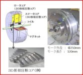
Speaking of grooves,.. I found this odd Japanese axial, with grooved magnets and core's. Whats up with that?
The web site had nothing to say about it, and at the moment, I can't see any reason for it.
Seems like a lot of work to go through, so they must figure that theres an advantage. :?:

Groved magnet and core.jpg

Has anybody seen groove's like this before? Maybe an attempt to increase area?
 
APL said:
I ordered out some axle aluminum, so at least I can get going on that. Hopefully I can do a better job this time
and get this thing to spin straight. I think the hardest part of turning the axel is to get the bearing ID to fit just
right, and wind up with somewhat of a press fit.

Other than that, I'm just trying to get back in the groove around here.

Speaking of grooves,.. I found this odd Japanese axial, with grooved magnets and core's. Whats up with that?
The web site had nothing to say about it, and at the moment, I can't see any reason for it.
Seems like a lot of work to go through, so they must figure that theres an advantage. :?:

Has anybody seen it before?

NTN, SKF suggest to have a tolerance of no more than 0.03mm. It's important that both bearings have no parallel misalignment, for that I would suggest turning the bearing area in one operation. Hopefully you have a DRO, micrometer to help you with that.
 
APL said:
Speaking of grooves,.. I found this odd Japanese axial, with grooved magnets and core's. Whats up with that?
The web site had nothing to say about it, and at the moment, I can't see any reason for it.
Seems like a lot of work to go through, so they must figure that theres an advantage. :?:

Has anybody seen groove's like this before? Maybe an attempt to increase area?

The only thing I can think of is it will improve the heat transfer from the stator to the rotor (probably a lot). I don't see any advantage from a magnetic standpoint.
 
I tried looking up any information that I could on it, but found nothing. Problem is figuring out what to call it.
They call it 3D pressed core technology, which doesn't help. I wound up on a lot of Japanese web sites, but never
found any reference's. So I guess it will remain a mystery. Heat transfer will do for now, although it would be nice
to have found some specs on that, since heat removal is a common subject here.

Original link; http://jan2018.tems-system.com/exhiSearch/INW/eng/Details?id=2sjaEvOHOWg%3D&type=2

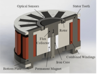
Another curiosity I found was this bearing-less motor,.. not an axial, but interesting anyway, since we all like motors. :)
Near as I can figure, the whole thing is built to spin the small 'ring' rotor thats held in a magnetic field. (visible in the
top center) Good for hart pumps,.. but not so much for bikes.

Bearingless motor..png

Bearingless link; https://triz-journal.com/patent-of-the-month-hysteresis-bearing-less-motor/
 
Would the magnetic bearing have cogging at all I suppose if it's all one field internally and externally the opposing field it would have the same frictional resistance from the magnets through out a full revolution but no cogging effect only from the rotor and stator themselfs with their segmented poles.

Question is at what point does a normal ball bearing become inefficient compared to the magnetic equivalent ? clearly cost and space rise with the later but service life is as long as the magnetism is strong enough so many years of trouble free life, this is one of the more interesting threads to me lots of technical knowledge that has to be managed into a state of the art prototype your definatly on the right track though pick the past apart to find the future.
 
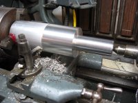
I finally got the aluminum bar stock I ordered the other day, and chucked it up in the little 1940's South Bend lathe.
She does a good job of turning it down all right, but sure ain't in any hurry. Gives me lots of time to think, and study
the plans, while the old leather drive belt chatters along.

At least it's getting built at long last. I've got a good feeling about this version, and it should be a far cry better than
the last one.
The only iffy part is how the core material is actually going to perform, and that can be changed with some other SMC
if need be, and won't affect the rest of the motor.

It's going to be fun trying this thing out when it's done, as I'm confident that we've covered all the bases this time.
Thanks for all the help! :thumb:

Axle start V2.jpg
 
APL said:
I tried looking up any information that I could on it, but found nothing. Problem is figuring out what to call it.
They call it 3D pressed core technology, which doesn't help. I wound up on a lot of Japanese web sites, but never
found any reference's. So I guess it will remain a mystery. Heat transfer will do for now, although it would be nice
to have found some specs on that, since heat removal is a common subject here.

Original link; http://jan2018.tems-system.com/exhiSearch/INW/eng/Details?id=2sjaEvOHOWg%3D&type=2

Here's the patent:
https://patents.google.com/patent/US9882442B2/en?q=company&q=powder&q=pressed&q=core&assignee=nippon+piston+ring&oq=nippon+piston+ring+company+powder+pressed+core
 
Wow, thats awesome wturber, I don't know how you found that! But it moves us forward on that motor at last. Only
problem is all the lawyer-patent talk, and trying to figure out what they are saying.

There seems to be two things going on here, first he says that the grooved teeth create more area, and thus torque, and
secondly, this particular motor patent has a spring system that varies the air gap between start up and run cycles.

The grooves;
An axial gap type BLDC motor of the present invention can rotate in a state where the first tooth parts and the second tooth parts that are respectively formed in the stator and the rotor in concavo-convex shapes engage with each other. Hence, an interlinkage magnetic flux of the motor of the present invention can be more than twice as large as that of a plane gap type motor, and torques thereof at the time of start-up and a low speed can also be more than twice. Moreover, the motor of the present invention generates lower noise compared with a conventional axial gap type motor.


And the spring mechanism;
Next, an operation of FIG. 1 is described. In a case where this rotating electric machine starts up a load, a maximum current according to a started load torque flows in the BLDCM. Because a larger attraction force in the axial direction is generated in the axial gap type motor than in the radial gap type motor, as illustrated in FIG. 1, the rotors on both sides are attracted toward the stator iron core part 1 with a predetermined minimum air gap, and start up. A spring constant of the coil spring 10 is set to such a value that the coil spring 10 is contracted close to a minimum spring length by the axial attraction force generated by the start-up current application and that the coil spring 10 pushes back and moves the rotor in the axial direction by a predetermined length at the time of no current application to the winding wire 2. As the speed of the rotor is increased after the start-up, the load current decreases. Hence, the gap attraction force also decreases to come into balance with the spring force, and the air gap length increases. As a result, a field weakening effect is produced, and the number of rotations can be increased. Detailed description thereof is further described later with reference to FIG. 9. It is important that the gap length and the generated torque linearly change, and the present invention is suitable in this regard, which is described later with reference to FIG. 8

Looking up other patents by Mr. Masafumi Sakamoto and his team, I see many other similar motor patents. These are some busy guys!
Who would have of thought that all this comes from a piston ring company?

Anyway,.. lots to digest here. "Interlinking magnetic flux can be more than twice as much as conventional"....really? :!:
Thats kind of huge.
 
APL said:
Wow, thats awesome wturber, I don't know how you found that! But it moves us forward on that motor at last.

Searched patents.google.com for the company name and general device description in the link.
 
APL said:
Who would have of thought that all this comes from a piston ring company?

You know the story of Zebco fishing reels - right? Zero Hour Bomb Co. They originally made timing / trigger mechanisms for "bombs". Actually explosives for fracturing geological formations in oil exploration. After the war and the drop in the need for oil, they needed to re-apply that tech and manufacturing capability somehow. Enter the switch to a new kind of fishing reel.

Some people learn lessons from history. Maybe this piston ring company employs that kind? :^)
 
APL said:
A spring constant of the coil spring 10 is set to such a value that the coil spring 10 is contracted close to a minimum spring length by the axial attraction force generated by the start-up current application and that the coil spring 10 pushes back and moves the rotor in the axial direction by a predetermined length at the time of no current application to the winding wire 2. As the speed of the rotor is increased after the start-up, the load current decreases. Hence, the gap attraction force also decreases to come into balance with the spring force, and the air gap length increases. As a result, a field weakening effect is produced,

Interesting way to do mechanical field weakening. These days I think you could skip that feature and just do it electronically with the controller.
The part about having twice the startup torque I'm skeptical about. I guess it depends on what you are comparing to, but a well made motor with a 1mm gap is not going to have much flux loss in the gap.
 
Wooooo, good start! I'm not envious of doing that on South Bend (10?). We used to have an early 1900's era Lodge and Shipley lathe that was given to us by a friend. While it was incredible that they were able to produce it at the time, it was severely lacking for modern machining, haha. We run an 80's era South Bend engine lathe for our manual machine now.
 
Fechter, I agree,..extraordinary claims require extraordinary proof, it would be nice to see some specs to back that up.
I wonder if anything would show up in FEMM. Besides,.. theres no free lunch, twice as much of one thing means more
of another. (usually drag, heat, losses.) Still, it's intriguing to understand what is really happening within the grooves
that would lend itself to higher torque.
It would be a manufacturing nightmare to try to keep all that stuff in alignment, and not touch anywhere.

Coleasterling, yea, it's a challenge alright, what takes me two or three days, you could pop out in an hour. Well, as the
old saying goes,.. "the ox is slow, but the earth is patient".
A friend of mine took me on a tour through a 'maker' place in town the other day. I was impressed, and I'm seriously
thinking of joining. They have all the toy's, mills, welders, laser cutters, you name it. But they also have a few bigger
lathes that I could really use for this project. This little So-B. is just no good for anything bigger than an axle.
 
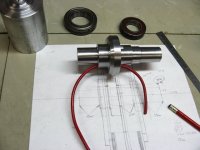
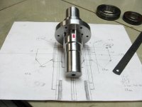
Some more progress on the axle,.. made out of a pice of 2.75" round stock, and turned out pretty good.
The bearing seats came out pretty good as well, although not a press fit. I decided against the idea, since it would be
such a pain to get them back off again, and it's really not necessary on a slow turner motor like this one anyway.

New axle  phase route .jpg

Drilling the phase wire holes was a snap this time, just a straight through-shot to the inner axle, and they even made
their own grooves for the wire bend. :thumb: So I don't have to mill slots for them.
I added a fourth hole, for sensor wires, since it's so easy to do, and I can use it for diagnostics like coil voltage readings,
temp sender, or hall wires.

Sensore hole..jpg

Drill and tap the axle ends, and she's pretty much done. Next up is the G10 stator plate, and then it's off to the rotors.
 
You do nice work with that little guy! You should add a china DRO and Aloris toolpost clone. Counting ticks and using indicators is fine, but it is so much faster with a DRO.

Really good progress!
 
I didn't know about aftermarket digital read outs for a lathe, so I checked a few of them out. That would be great,
I especially like the zeroing feature, to reset at any point.
It would be kind of a waste on this little first gen. 9" lathe,.. although I could always transfer it over to the next lathe.
After having this one for a year now, I realize that I should have bought the bigger 10" 'heavy' instead, it's ten times
the lathe this one is. That will be the next endeavor, and a DRO would be right at home on that one.
A decent tool post, and a new chuck have been on the wish list for quite a while now, but I just keep limping along.
Never fails,..every time you buy a tool, you realize what you should have bought instead. :roll:

Hey coleasterling, check your Endless Sphere inbox mail, I sent you a message. Hopefully we can get started on the
cores for this thing at some point,.. depending on how much time you have.
I have plenty of things to make yet, and I'm thinking of 3D printing a few cores first, just so I can wrap some wire on
them and check the fit. I'll probably print a 'thin' stator plate too, to make sure they fit correctly on that as well,
and get the spacing exactly right.
 
APL said:
I didn't know about aftermarket digital read outs for a lathe, so I checked a few of them out. That would be great,
I especially like the zeroing feature, to reset at any point.
It would be kind of a waste on this little first gen. 9" lathe,.. although I could always transfer it over to the next lathe.

An other, cheaper way to achieve almost the same thing is to purchase some cheap metal calipers. You can find some for around 10-15 bucks. Just cut the lenght you need and figure out a way to install it on your lathe's axis. This way you get some relatively accurate measurings, an easy way to zero everywhere you want, actual backlash compensation as well as quick conversion between imperial/metric.
It costs peanuts, only a few hours of your free time to install them on the lathe, but that's some time saved later when turning stuff! :wink:

If you go for cheap calipers, just make sure that you have plenty of spare batteries. That's the drawback on these cheap devices, they use a lot more current event when powered off and they will lose accuracy dramatically when the battery is empty (takes a few month though). But when the battery is good then they are precise enough for any application, except maybe some rocket/spaceship project :wink:
 
Great idea, especially if I get the long version calipers. Put some magnetic bases on it and I'm good to go,.. as long
as I can zero it out. I'll have to check into it. Just right for 'this' old lathe. Thanks. :thumb:
 
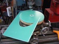
I got the 1/4" G10 Garolite in the mail, about $35. for a square foot of it. Stuff is pretty heavy, I might as well use
plate glass, if I could cut it. But at least it's solid enough,.. the stuff is darn near bullet proof.

I couldn't fit it into the lathe at that size, so I mounted it to a cheap rotary index table I scored at the swap meet this
spring, and spun it on the mill by hand.
That actually worked really good, and I was able to get a perfect disc, and center hole out of it. Since the stator won't
be spinning, it doesn't need to be any better than that.

Carier cut..jpg

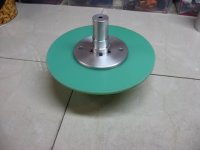
Then I made a washer/brace to be bonded to the other side, so that the mounting screws don't crush the Garolite when
they get tightened down. A little overkill, but better safe than sorry. I still have to drill and tap some screw holes yet.

View attachment 1

So I guess now I'm waiting to get some cores 3D printed so I can check the fitment of the coil wire on them, and make
sure that they're good to go for machining.
(I wonder if I could make it an air coil motor this way,..with plastic cores) :?:
Just a thought.

Stator assembly.jpg

I guess it's time to start thinking about rotors already.
 
Great job on the disk. That stuff looks good. The real issue will be deflection when the magnets get close to the cores, but the magnetic forces should be largely balanced.
 
Back
Top