
Hi everyone,
Just wanted to share a project I'm working on to see if anyone has attempted anything similar or is just interested. I am building a performance / battery monitor for a small electric vehicle and I'm using the Arduino Mega ADK R3 to interface between the vehicle and the sensors / battery, as well as to connect to a Google Nexus 7 tablet. I figured a clean solution for measuring cell voltages would be a custom Arduino shield.
This design uses two TI BQ76PL536A battery monitors / protection ICs (http://www.ti.com/lit/ds/slusam3/slusam3.pdf).
Here are the current implemented features for the Mega Shield (as of August 2013):
As of August 2013, the Mega shield has been put on hold to develop a shield for the Arduino Uno, because I think it is much more popular. Once the Uno shield is finished, it can be blown up to the Mega dimensions and slightly rerouted.
Here are the features that are being added to the Uno board:
The thread will be updated with newer entries first.
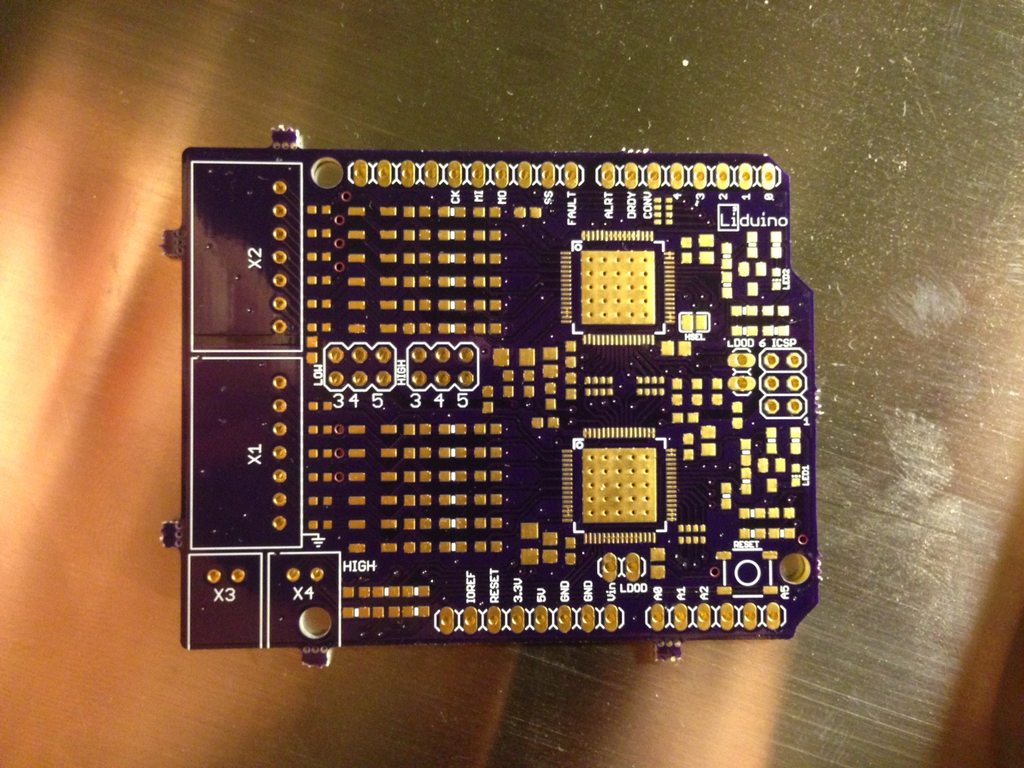
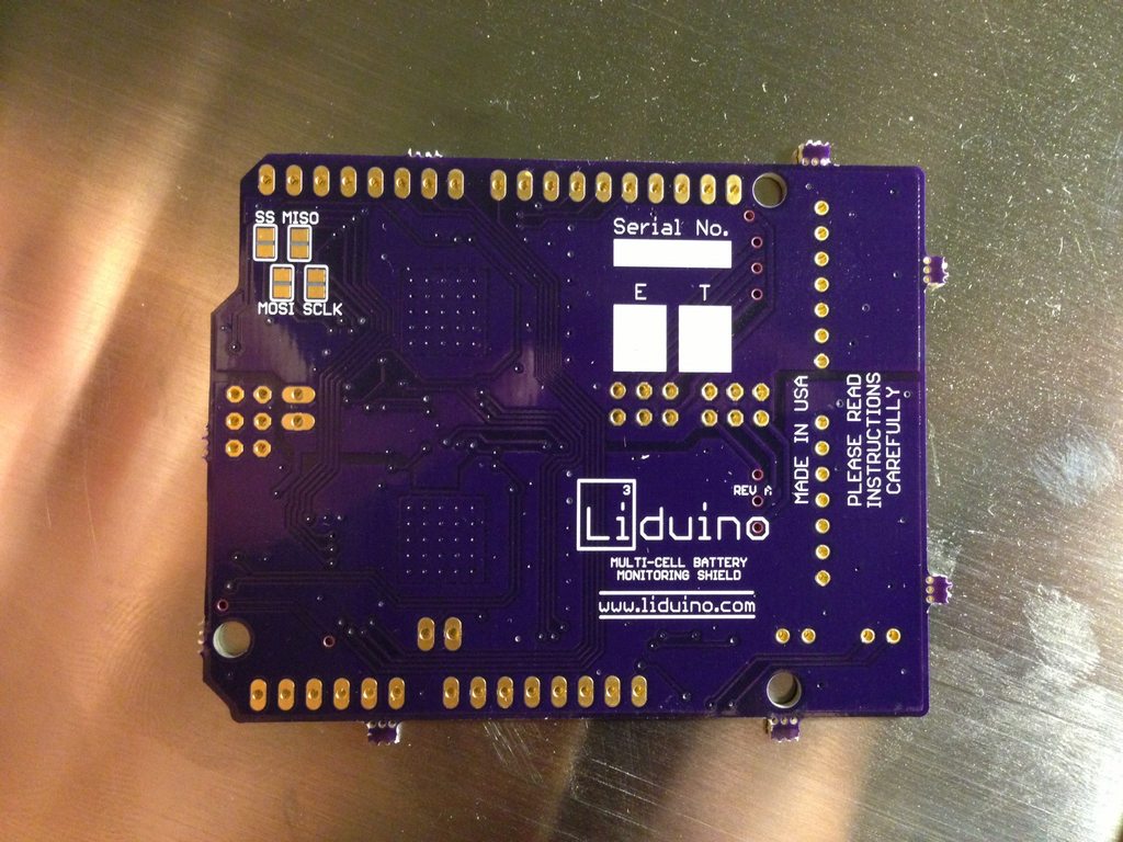
UPDATE: 9/16/2013
Hey everyone,
Just got the PCBs back from OSH Park and they look great. Here are some pictures:
http://imgur.com/a/TdqGv#6KqZs40
Tonight I will be ordering the parts I need and trying to make a solder stencil. Wish me luck!
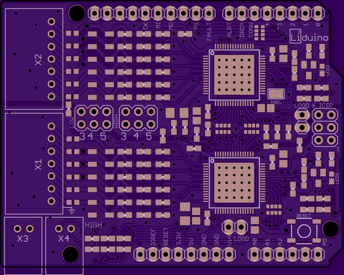
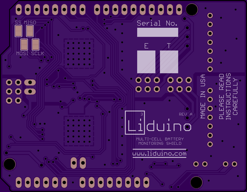
UPDATE: 9/3/2013
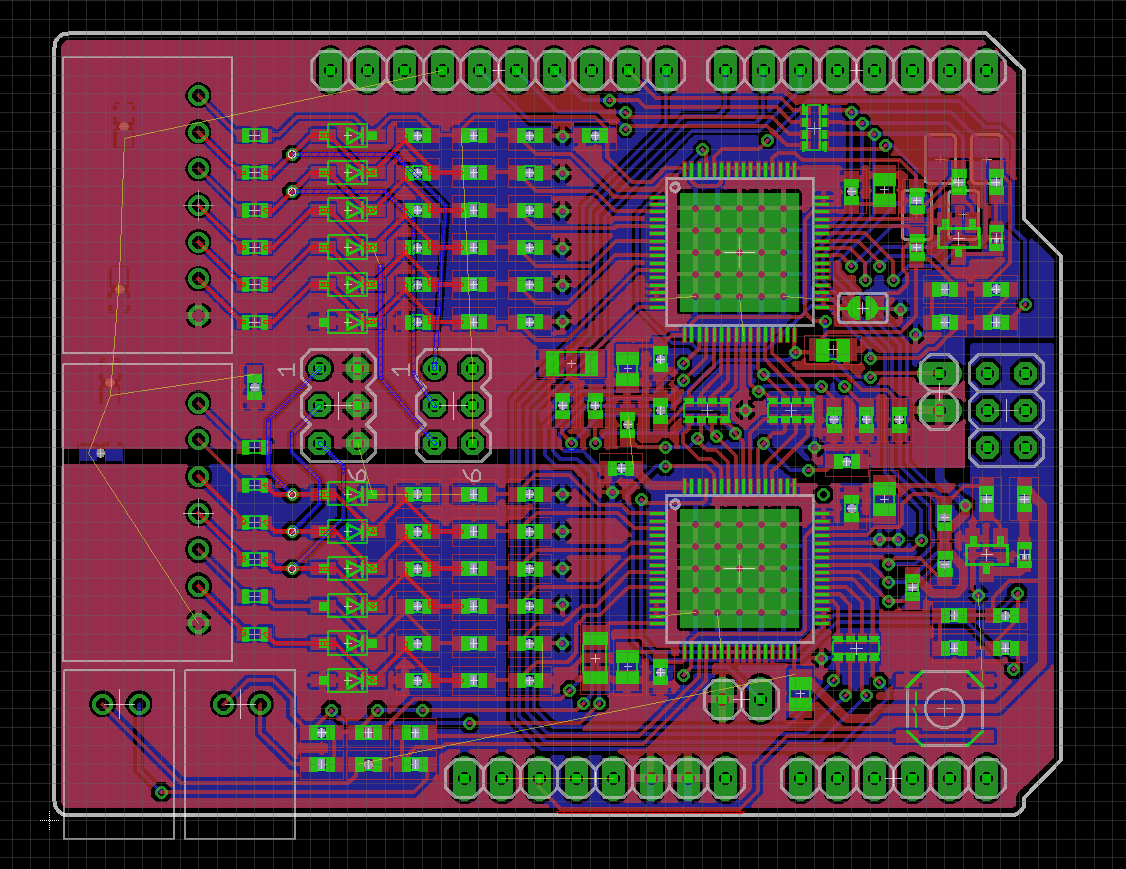
Just submitted the finished PCB to OshPark. I should get the boards within two weeks or so. In the meantime, I will work on programming firmware on the old Mega board. Check it out below!
http://imgur.com/a/GaafQ#BHyFR0V
UPDATE: 8/30/2013
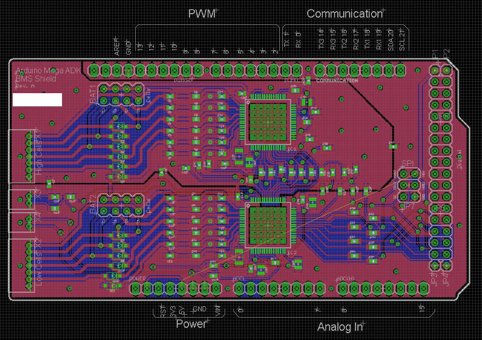
I'm still active and making good progress. The board should be finished and ordered by the end of the weekend. Here is a teaser, with some details left to route:
Again, it would be very helpful if you would let me know if you're interested in this board when it becomes available.
I thought it would be fun to do a comparison, so here is the price of the BMS shield, compared to the equivalent price to get the same features from TI (Note that TI supports 18 cells, but the board is gigantic):
Equivalent features from TI
Arduino Uno BMS Shield
UPDATE: 8/9/2013
Just wanted to let everyone know that this project is still active and I have my sights set on a small run available to ES users.
Right now I am working on a Rev B shield for the Arduino Uno instead of the Mega. The board size will just be increased for the Mega. So far I have implemented:
- LED indicators for each chip (programmable through SPI)
- XH connectors instead of ZH (balance taps on most batteries)
- Utilization of both temperature ports on both chips (one measuring chip temperature and external temp per chip)
- Resettable PTC fuses on inputs for cell shorting protection
- Resistor arrays instead of individuals (for my benefit)
I'm still working on:
- Optional ability to reprogram EPROM on chips to set under and over voltage limits
I'm looking at a final price of $100-$120 per board (shipped), which might seem steep, but it will include functions only available on the $200 chip reprogrammer. At a larger scale, the cost will come down.
Stay tuned and let me know if you have suggestions!
UPDATE 3/27/2013
So I had some problems talking to the upper IC. It was putting out 10V on one of its 5V outputs, so I investigated with an employee from TI and a friend of mine, and we determined that the REG50 pin requires a 2.2 uF capacitor for the IC to function. We air-wired this cap between the pin and ground and the board now successfully measures battery voltage from both chips. I'm very excited, as the competition is next weekend and I wasn't sure if this was going to work.
Next I am converting my code into a library so the main Arduino sketch can be cleaned up. If anyone has any questions or is pursuing a similar project, feel free to ask.
UPDATE 3/6/2013
I guess some of the diodes were exposed to a voltage surge, either static or me connecting the batteries incorrectly. Anyway, two more of them were blown and had to be replaced. I am now able to connect through the Arduino and read/write to the different registers. I am getting accurate simulated voltages for each cell. I guess that means the board is a success so far. I attached some pictures of the setup:
Click for complete album

Next I might write the code as an Arduino library. I want to add an algorithm for chip addressing and make the code more expandable. Stay tuned!
UPDATE 3/4/2013
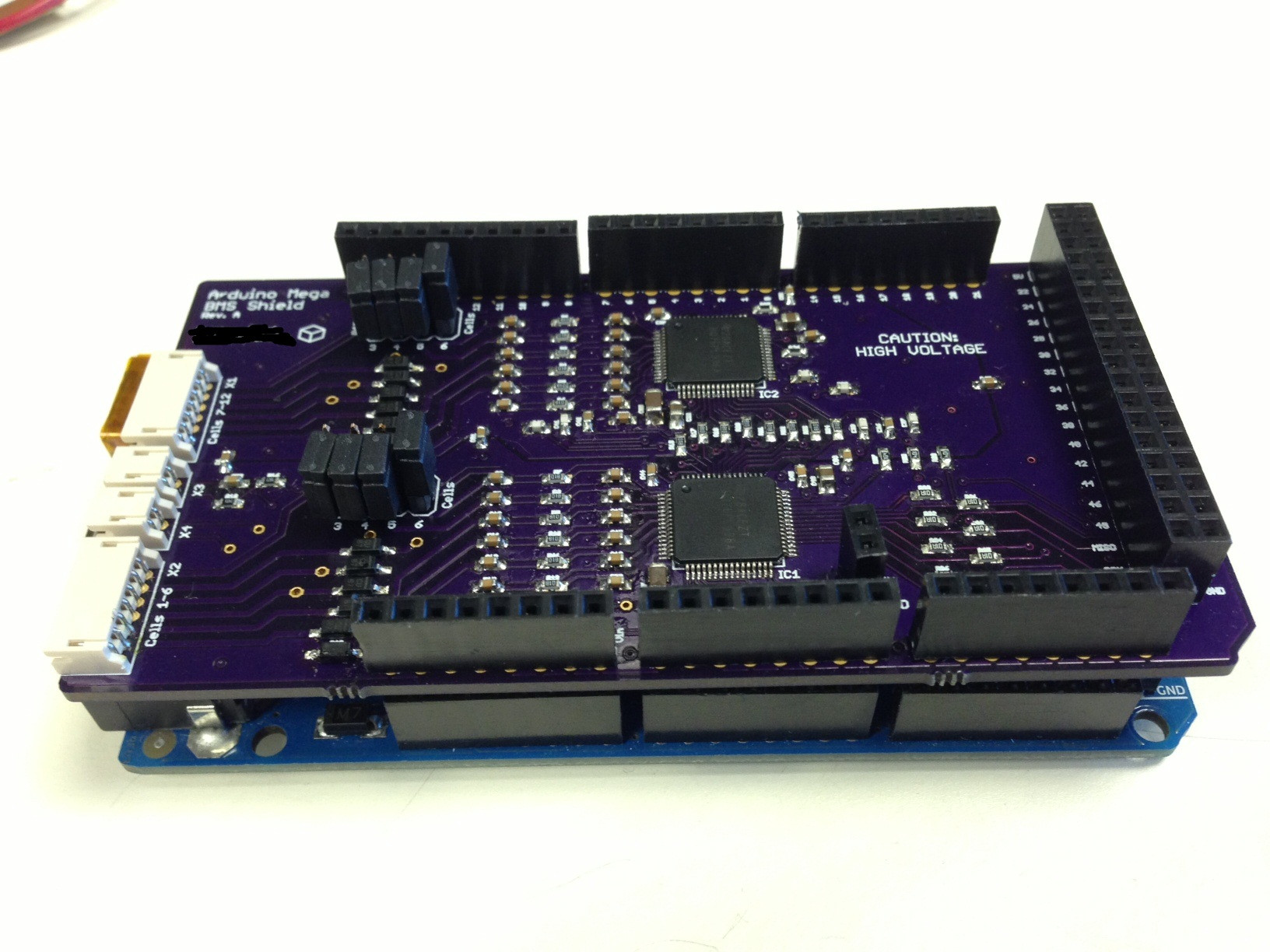
So I investigated the short, turns out it was a faulty diode between the input of cell 1 and ground. I replaced the diode and the short is gone. Here is a picture of the Arduino shield on the BMS:
UPDATE 3/2/2013
So I placed all the parts, and I've been testing the board with a Sparkfun SPI shortcut and connecting it directly to the Arduino board. For a while I was getting the same hex message over and over, but I realized I made an error connecting my batteries (for now I'm using 9 volts in series, divided over several cells). The fault and alert pins are active, which means the chip is working but something is wrong. Im getting unique messages now, but there are programming challenges so I will be collaborating with a friend to try to fix them. I eventually discovered that somehow the bottom cell input is shorted to ground, which is likely causing some problems. I will try to fix it tomorrow, but if I don't have luck, I will have to place parts on another board. Luckily I think the PCB itself is ok (no shorts on either of the bare PCBs in that area).
UPDATE 2/25/2013
I ordered the boards from OSH Park about two weeks ago and I received them within a week. They look great! It was $50 for three boards.

I ordered parts and I hope to have the boards completed by the end of the week.
Just wanted to share a project I'm working on to see if anyone has attempted anything similar or is just interested. I am building a performance / battery monitor for a small electric vehicle and I'm using the Arduino Mega ADK R3 to interface between the vehicle and the sensors / battery, as well as to connect to a Google Nexus 7 tablet. I figured a clean solution for measuring cell voltages would be a custom Arduino shield.
This design uses two TI BQ76PL536A battery monitors / protection ICs (http://www.ti.com/lit/ds/slusam3/slusam3.pdf).
Here are the current implemented features for the Mega Shield (as of August 2013):
- Supports 6S-12S packs (22.2V - 44.4V nominal), each BQ chip can take 3-6 cells
- Communication between BQ chips and Arduino via SPI
- Two battery temperature inputs
- Battery connection to enclosure via JST-ZH connectors
As of August 2013, the Mega shield has been put on hold to develop a shield for the Arduino Uno, because I think it is much more popular. Once the Uno shield is finished, it can be blown up to the Mega dimensions and slightly rerouted.
Here are the features that are being added to the Uno board:
- Smaller board compatible with Arduino Uno!
- PTC fused cell inputs
- ICSP header accessible on top shield
- All four temperature inputs are utilized (two external via JST-XH, two on PCB)
- Connection from BMS to battery pack via more common JST-XH connectors
- Two surface mount LEDs on PCB, to be used for debugging/alerts
- Arduino reset button on shield!
- Ability to program OTP EPROM to set default under-voltage, over-voltage, cell imbalance, and temperature settings using reprogrammer dongle (available in the future)
The thread will be updated with newer entries first.
UPDATE: 9/16/2013
Hey everyone,
Just got the PCBs back from OSH Park and they look great. Here are some pictures:
http://imgur.com/a/TdqGv#6KqZs40
Tonight I will be ordering the parts I need and trying to make a solder stencil. Wish me luck!
UPDATE: 9/3/2013
Just submitted the finished PCB to OshPark. I should get the boards within two weeks or so. In the meantime, I will work on programming firmware on the old Mega board. Check it out below!
http://imgur.com/a/GaafQ#BHyFR0V
UPDATE: 8/30/2013
I'm still active and making good progress. The board should be finished and ordered by the end of the weekend. Here is a teaser, with some details left to route:
Again, it would be very helpful if you would let me know if you're interested in this board when it becomes available.
I thought it would be fun to do a comparison, so here is the price of the BMS shield, compared to the equivalent price to get the same features from TI (Note that TI supports 18 cells, but the board is gigantic):
Equivalent features from TI
- BQ76PL536EVM-3 Evaluation Board - $203 on Digikey
- BQ76PL536PGM-1 Programming Board - $203 on Digikey
- Aardvark I2C/SPI Host Adapter - $275 on TotalPhase
Total - $681
Arduino Uno BMS Shield
- Uno BMS Shield - $100-120 (price TBD)
- Arduino Uno - $22 on Amazon
Total - $122-142
UPDATE: 8/9/2013
Just wanted to let everyone know that this project is still active and I have my sights set on a small run available to ES users.
Right now I am working on a Rev B shield for the Arduino Uno instead of the Mega. The board size will just be increased for the Mega. So far I have implemented:
- LED indicators for each chip (programmable through SPI)
- XH connectors instead of ZH (balance taps on most batteries)
- Utilization of both temperature ports on both chips (one measuring chip temperature and external temp per chip)
- Resettable PTC fuses on inputs for cell shorting protection
- Resistor arrays instead of individuals (for my benefit)
I'm still working on:
- Optional ability to reprogram EPROM on chips to set under and over voltage limits
I'm looking at a final price of $100-$120 per board (shipped), which might seem steep, but it will include functions only available on the $200 chip reprogrammer. At a larger scale, the cost will come down.
Stay tuned and let me know if you have suggestions!
UPDATE 3/27/2013
So I had some problems talking to the upper IC. It was putting out 10V on one of its 5V outputs, so I investigated with an employee from TI and a friend of mine, and we determined that the REG50 pin requires a 2.2 uF capacitor for the IC to function. We air-wired this cap between the pin and ground and the board now successfully measures battery voltage from both chips. I'm very excited, as the competition is next weekend and I wasn't sure if this was going to work.
Next I am converting my code into a library so the main Arduino sketch can be cleaned up. If anyone has any questions or is pursuing a similar project, feel free to ask.
UPDATE 3/6/2013
I guess some of the diodes were exposed to a voltage surge, either static or me connecting the batteries incorrectly. Anyway, two more of them were blown and had to be replaced. I am now able to connect through the Arduino and read/write to the different registers. I am getting accurate simulated voltages for each cell. I guess that means the board is a success so far. I attached some pictures of the setup:
Click for complete album
Next I might write the code as an Arduino library. I want to add an algorithm for chip addressing and make the code more expandable. Stay tuned!
UPDATE 3/4/2013
So I investigated the short, turns out it was a faulty diode between the input of cell 1 and ground. I replaced the diode and the short is gone. Here is a picture of the Arduino shield on the BMS:
UPDATE 3/2/2013
So I placed all the parts, and I've been testing the board with a Sparkfun SPI shortcut and connecting it directly to the Arduino board. For a while I was getting the same hex message over and over, but I realized I made an error connecting my batteries (for now I'm using 9 volts in series, divided over several cells). The fault and alert pins are active, which means the chip is working but something is wrong. Im getting unique messages now, but there are programming challenges so I will be collaborating with a friend to try to fix them. I eventually discovered that somehow the bottom cell input is shorted to ground, which is likely causing some problems. I will try to fix it tomorrow, but if I don't have luck, I will have to place parts on another board. Luckily I think the PCB itself is ok (no shorts on either of the bare PCBs in that area).
UPDATE 2/25/2013
I ordered the boards from OSH Park about two weeks ago and I received them within a week. They look great! It was $50 for three boards.
I ordered parts and I hope to have the boards completed by the end of the week.
")