After many many months of hard work, technical discussions, documentation and tests we have come to the point we think we have the best platform for high power motor control.
Before hardware news, the BIGGEST news about this project is the formal presentation of the team that made it possible. Forum legends
HighHopes and
Arlo1 are deeply involved in the design, we have been working together on getting this control board out, and we founded www.powerdesigns.ca to centralize all the contract work we have been doing together as separate companies.
So what does this means? Arlo1 provides the field experience with his awesome, record-setting builds and tooling while HighHopes provides deep insight, his power systems knowledge and hard math to every design decision, while Maxi and I do what we do best, engineering, CAD, firmware and manufacturing. And remember this is standing on years of Benjamin Vedder's firmware development, to which we are already collaborators.
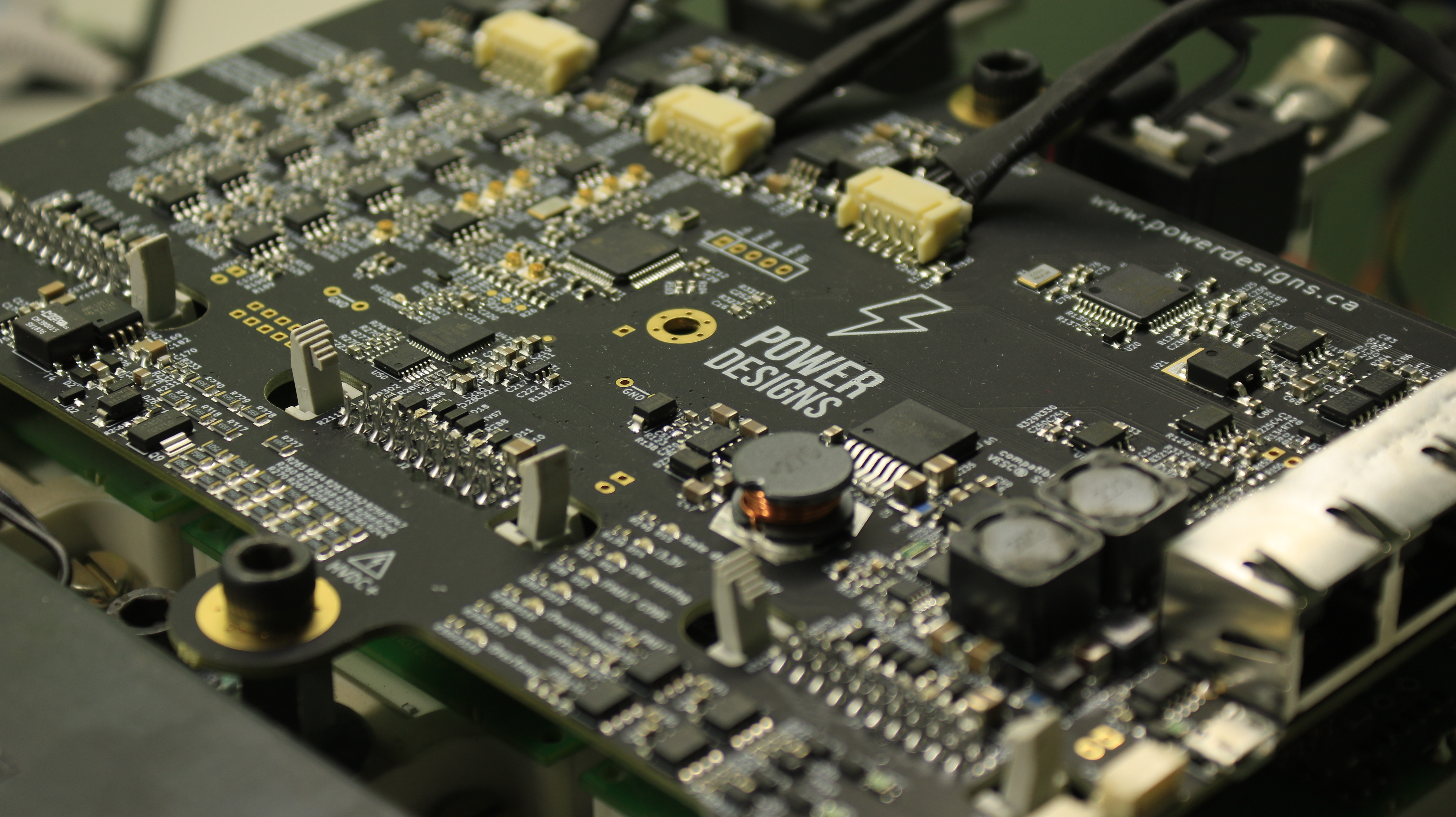
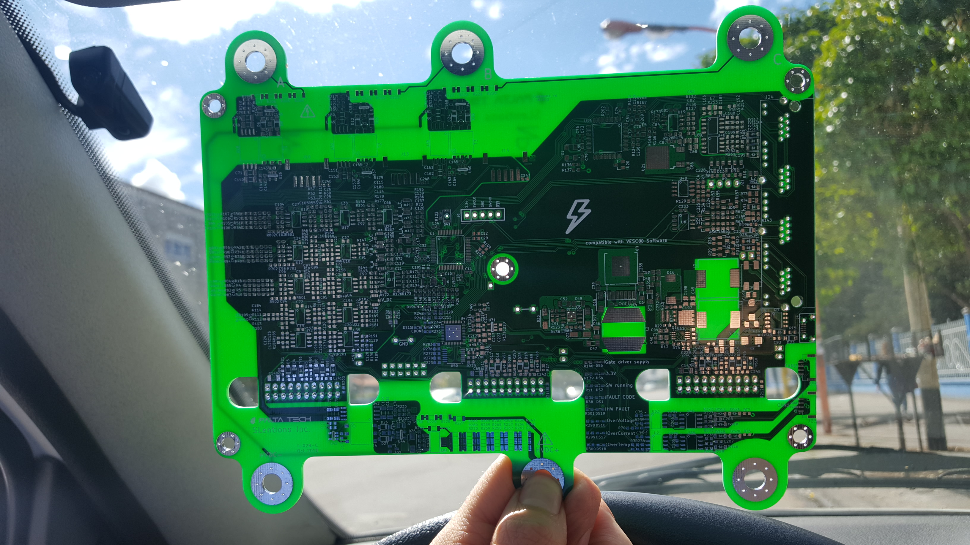
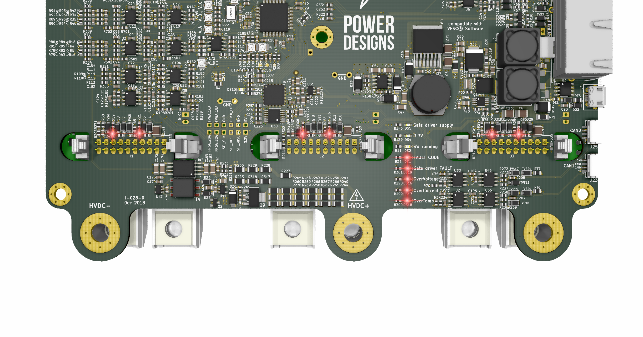
So, now to the hardware. Its black!
it also comes with in an interesting changelog
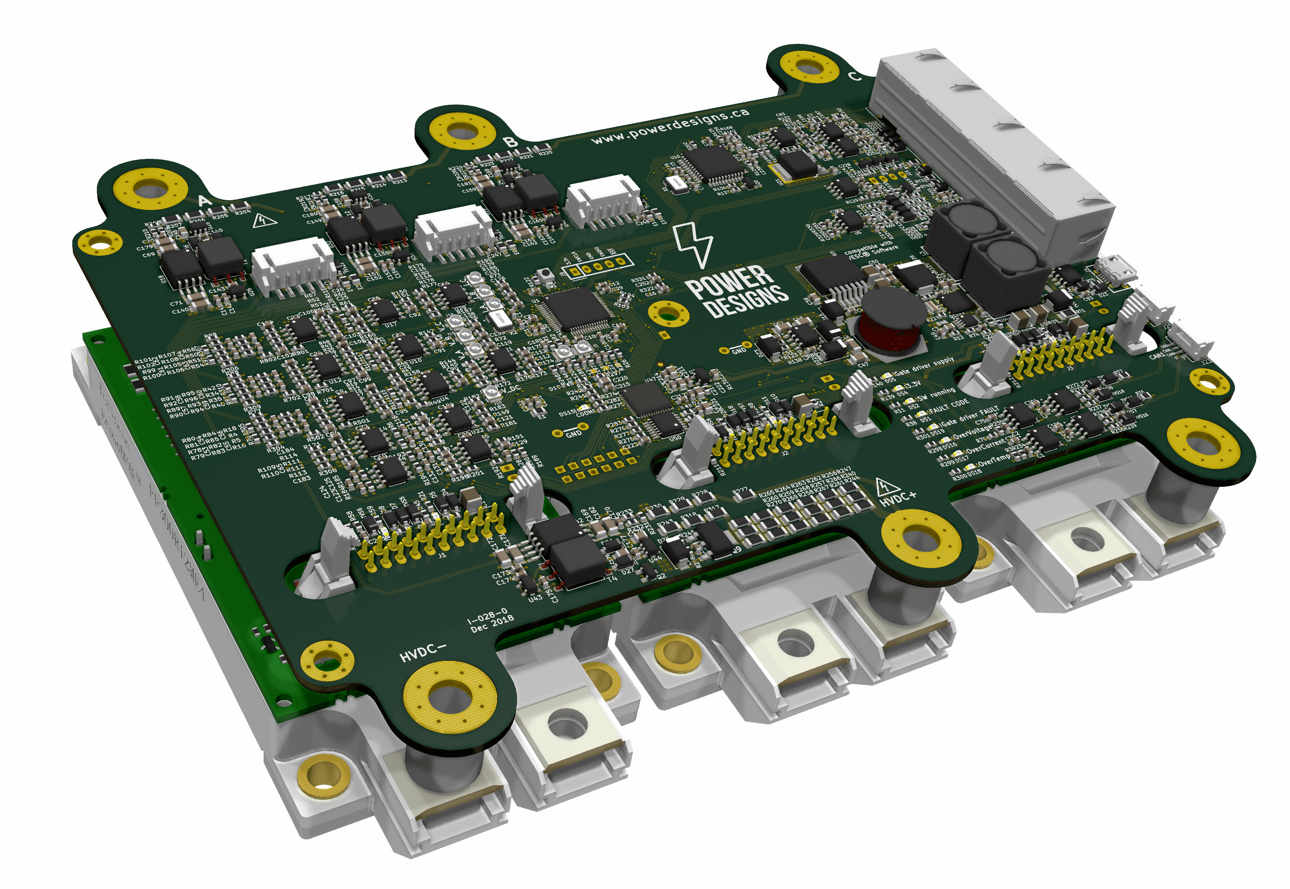
[*] Mechanically matched to EconoDual/17mm IGBT modules. No adaptor PCB needed.
[*]
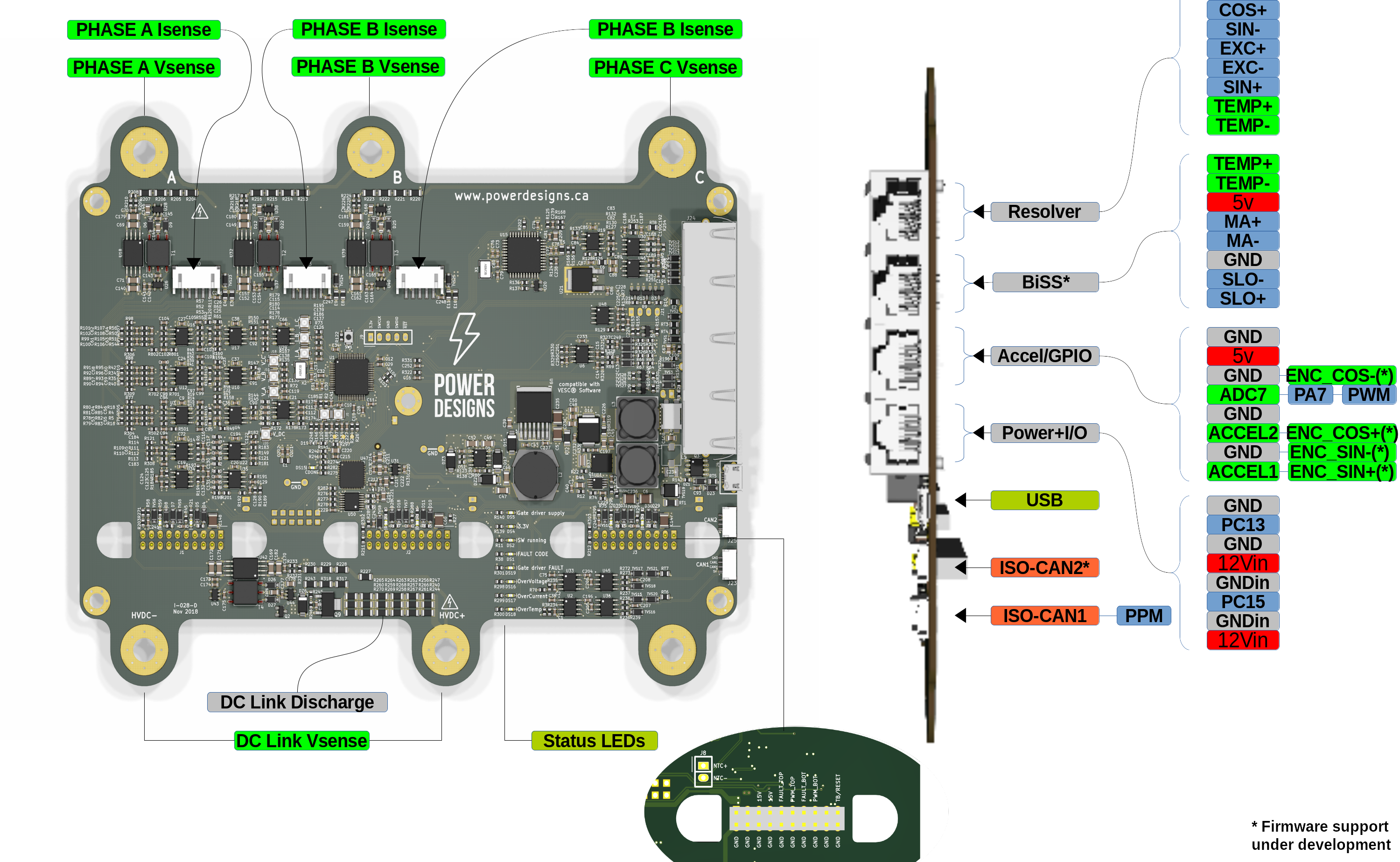
Isolated HVDC and phase voltage monitoring integrated on board.
[*] DC Link Capacitor discharge resistor on board. Discharges it when board is not powered.
[*] RF connectors to measure analog signals. This provides simulation-like signal quality, extremely cool for development.
[*] Individual IGBT fault monitoring. You can tell which IGBT faulted.
[*] Individual fault leds for overvoltage, overcurrent and overtemperature.
[*] Individual IGBT temperature monitoring.
[*] An FPGA is continuously monitoring all fault inputs. If any fault is asserted, all PWM activity is shut down.
[*] FPGA supervises the PWM generated by the MCU. Shuts down PWM if a shoot-through command is detected.
[*] RJ45 ports. These are not ethernet, they provide a shielded, twisted pair wiring in a standard off the shelf fashion.
[*] Dual analog Accelerator inputs.
[*] Dual isolated CANbus interfaces (firmware no there yet for the 2nd interface).
[*] Resolver support.
[*] BiSS absolute encoder support (firmware under dev).
[*] Sin/Cos encoder support.
[*] Supplies a regulated 15Vdc to the gate drivers, and monitors that voltage.
[*] 2 DAC outputs with RF connectors to peek inside the firmware.
[*] 2 Open drain outputs for driving small loads or relays, for a pump for example.
[*] More fuses, more TVS, more EMI filtering.
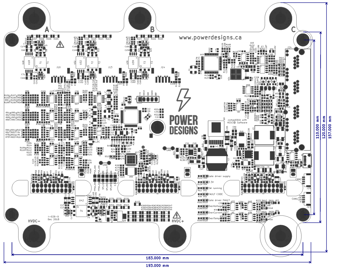
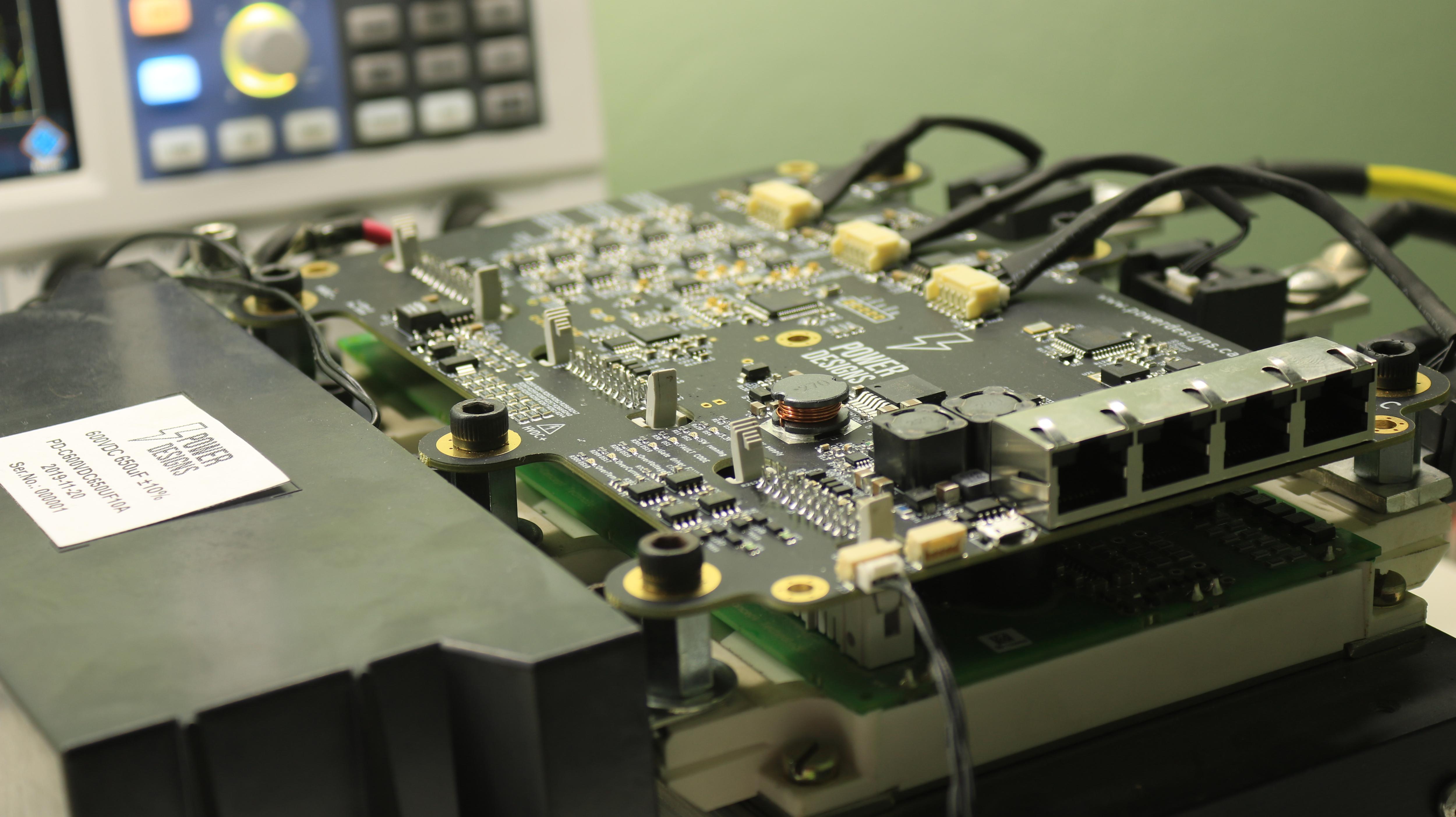
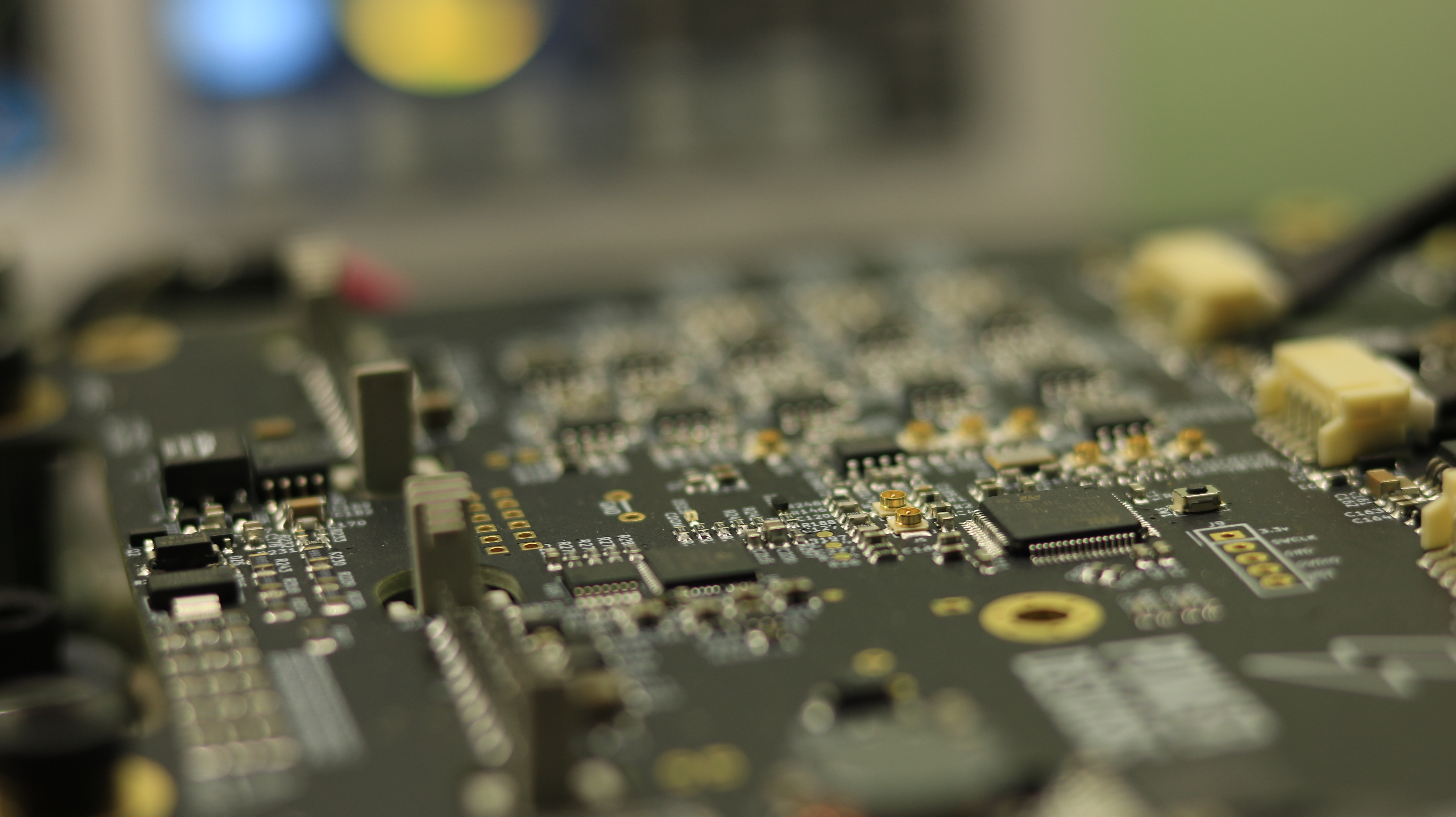
Here are some high-res images for reference:


An old prototype that can show the isolation cleareances. With newer boards you don't see through the thick soldermask

A sensorless full speed reversal with an IGBT-based powerstage: (yellow trace is the observer phase being output to a DAC channel)
View attachment 2
Many full speed reversals:

This is an exercise on the signal quality of the the board, in practice we strongly suggest to use absolute encoders on high power builds.
Crystal clear signals measured right at the ADC pins, and phase angle sent over the DAC to the scope

Clear fault reporting
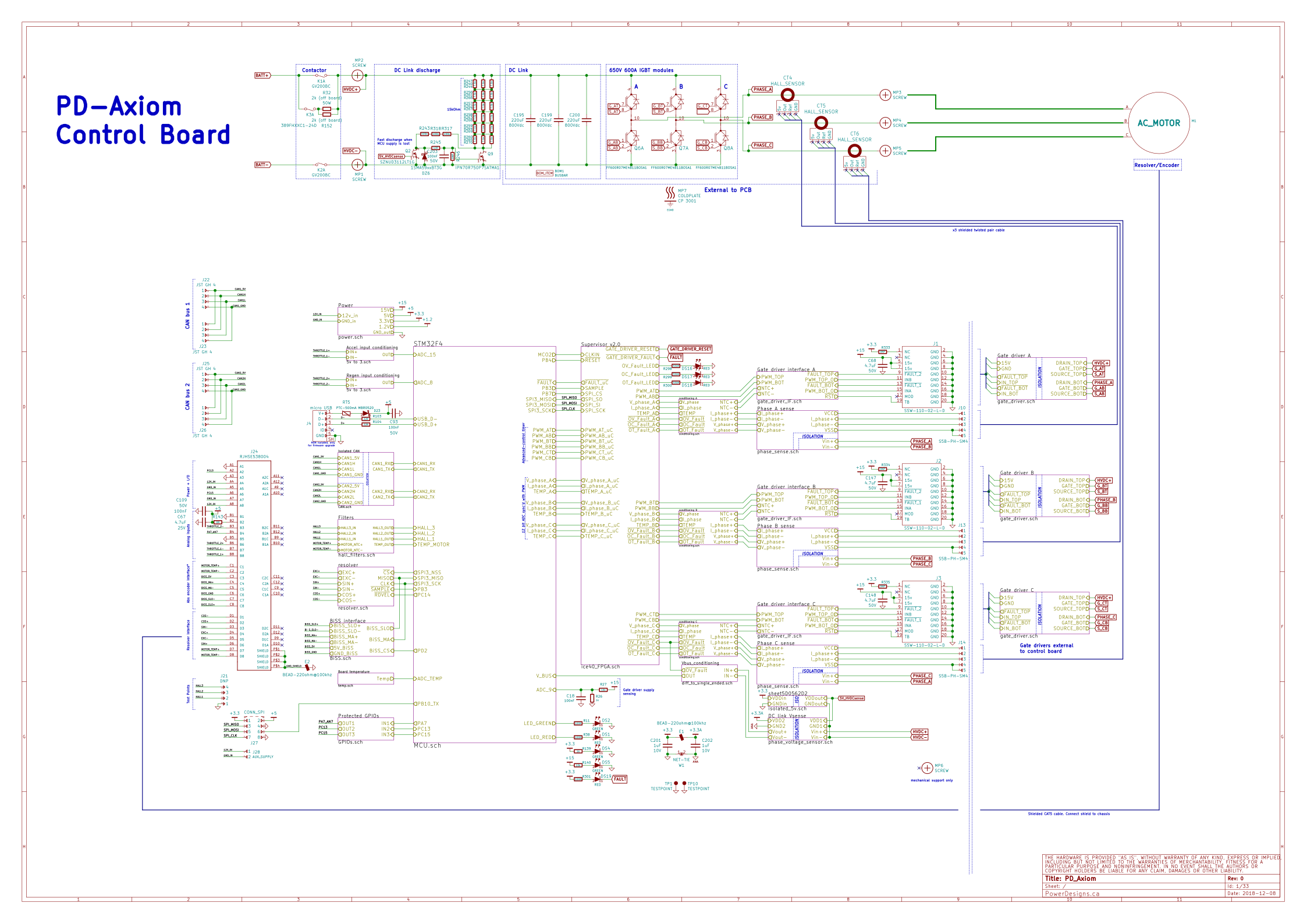
Schematic top level:

Click on the image for an interactive BOM viewer


More data, board datasheet and images will be available at www.powerdesigns.ca, as well as schematic and other design files. The build in the pictures is designed for 400V 300Amp continuous operation.
PowerDesigns should provide the assembled boards to anyone interested. We can offer bare PCBs on demand but the risk is so high and I didn't see a successful build when people have to assemble the boards, so its better if we take care of the assembly. Its even much better if we provide the complete motor controller, we are working on providing that option.
This controller will compete in 2019 Hackaday contest so we'll be extremely appreciative if you express your support to the project and us by following and liking it on its project page that we just posted:
https://hackaday.io/project/164932-axiom-400v300a-100kw-motor-controller
Maxi (co-founder engineer at paltatech) and me switched gears some months ago to firmware developing and testing when the hardware design was settled, meanwhile some alpha users start putting some miles on this, not many miles actually, we are still craving for testers and we don't claim it comes without bugs. All the code we provide for these high power applications is carefully crafted for direct integration into the VESC codebase so it stays public and well maintained.
Hardware-wise, we have math for finely setting our trip points, which we can easy tune at will by changing resistors, and the FPGA is a very powerful addition for co-processing and safety functions. We went as far as designing our own DC Link with an OEM, shown in the pictures and still under testing.
Its quite a compact and tidy unit.
This is an awesome platform for research and for high power builds, I don't know of any controller at this power level, with this quality and attention to detail while open to the user to modify the firmware at will.
We have been going on for a long way without external feedback, so I'm eager to hear what you guys think. Just remember this is not meant to be a cheap controller, its meant to drive very expensive and dangerous equipment, so it should be a safe and solid piece of hardware.

")