Axiom: a 100kW+ motor controller

I now have no faults - needed a HV supply to clear the fault...…….now I need one with some grunt so I can actually do something with it!
 
bigdaveakers said:
Marcos, are you able to provide details on the fault codes?

I have the fault light flashing when I power up the board and I am keen to debug.

I have connected the throttle and I am able to calibrate it and see the throttle input working in the VESC input wizard.

I haven't been out to my motor to check the resolver yet but I have wired up the gate drivers. I don't have an HVDC supply to connect at the moment so I am just checking out all of the low voltage stuff.
Sorry, didn't reply because I saw you already figured it out, but I didn't want to leave the question open. I just checked the fault codes in the code, and they are not coded! I copied the "fault code" silkscreen text from an official vesc board, I guess its in someone's TODO list. Its very simple to code this up here, but my time is better spent in safety critical code and EMI countermeasures.

On other news, motor simulator was merged into mainstream repository a few days ago, so its available for anyone that upgrades its firmware.
As a reminder, in these comments are the steps to make it spin, virtually.
https://github.com/vedderb/bldc/pull/82#issuecomment-480506937

sin/cos cos encoder support is merged as well, but only enabled on Axiom builds.

I have been working on another pull request these days, that most directly affect these high power builds:

Flash memory integrity checks.

Abricosvw and myself saw occasional flash memory corruption during operation. Its not occasional for Abricosvw, its most of the time but I believe its because of his wiring layout. I think I saw corruptions in my bench when I messed up during development and had faults with 1000+Amp flowing a couple centimeters away from the control board. Yesterday I found out that Benjamin also experienced this in the past.
I already added mechanisms to avoid flash operations when supply conditions are not ideal, but now I'm adding 3 new changes:
1. Lock flash memory operations when its not being used. I found it was kept unlocked all the time and that may be the reason of the corruptions. I couldn't reproduce corruptions for many months now, but maybe abricosvw can check this.
2. Add a CRC check to the firmware image. If on boot the calculated CRC doesn't match the stored CRC, don't execute code, as its not safe.
3. And now the cool one: Now we have a new thread that slowly crawls over the entire flash image continuously checking the integrity of the code in the background, while VESC is running. It spends about 1% of cpu time into this task, if CRC doesn't match the mcu is reset. So if your motor is running and Axiom is blasted with a flash-corrupting EMP, it will notice in a few seconds and halt operation.

And if you have the wimpiest VESC on the wimpiest bike, it will also sport some fancy flash integrity checking =D

The full discussion, code and profiling is in the Pull Request:
https://github.com/vedderb/bldc/pull/87
 
Continuous flash memory CRC check was merged a few of days ago!

In the hackaday project page I'm logging the new *merged* features, while here you get to know the new features before they are merged.

Next pull request in the line is the detection of current sensor failures
https://github.com/vedderb/bldc/pull/88

Now firmware will trigger a fault condition if current sensor offsets are too large, most likely because a disconnected sensor, and it will report which of the 3 sensors is faulty.

The other new fault condition is a high current unbalance between phases. Under normal operation, the sum of currents Ia+Ib+Ic must be limited, you can have a bit of unbalance but if it goes too high then there is something wrong.

unbalance fault.png


Quick video of sensor fault detection
[youtube]nkkPLbIC2JI[/youtube]

We are doing quite well in the hackaday contest, we jumped to the first place in the leaderboard, woot!
 
Yay!
Screenshot_20190425_091453.png


Benjamin added a way to store custom information in flash, I might use that to store current sensor gain, which is currently hardcoded and not exposed to the gui, so I have several binaries for each current sensor part. I should fix that soon.
 
This looks awesome! I've been kicking around the idea of an e-motorcycle conversion on a classic bike for a while and this looks like just the ticket. I'll need to get some VESC6 experience on a smaller scale first, but I'm excited!

I know in the past the VESC firmware couldn't use IGBTs for switching elements due to the way it did auto-detection of some motor parameters; does this mean that IGBT support is now in the base firmware and could be used by smaller scale derivatives?
 
SRFirefox said:
I know in the past the VESC firmware couldn't use IGBTs for switching elements due to the way it did auto-detection of some motor parameters; does this mean that IGBT support is now in the base firmware and could be used by smaller scale derivatives?
Its actually not a firmware issue, its the hardware. I can assure there is no other vesc out there that can properly work with IGBTs like Axiom does and that's 100% thanks to HighHopes being in the team, I couldn't have figured that out by myself.

In other news, current sensor failure detection has been merged, and I can store the current sensor gain with the vesc terminal, no more hardcoded binaries!

We should have some cool news next week, and Tec, we found an issue with your motor model, PR with the fix coming soon.
 
Hey marcos

From where i can donwload the gerbers and bom for the AXIOM. I cant wait to put that in my bike. [emoji7]

My bad luck today i got parts from digikey for vesc controller and i will start to build that one on sunday. Its my first smd based project but i will try my best. Wish i could have wait for AXIOM.[emoji21]

Sent from my COR-AL00 using Tapatalk


marcos said:
We should have some cool news next week, and Tec, we found an issue with your motor model, PR with the fix coming soon.

Whoot :shock: ok I'm eager to know whats wrong.
 
Hackey said:
From where i can donwload the gerbers and bom for the AXIOM. I cant wait to put that in my bike. [emoji7]
Its my first smd based project but i will try my best
Gerbers are not available ATM, I fear the production of chinese boards with cheaper or poorly assembled components. You know, the people dying with an cheap axiom clone problem. For example I found one place where a solder blob can compromise the isolation between powerstage and control domain.
This follows the same principles stated for the original VESC hardware, they had the same issue, with less dangerous hardware though:
https://vesc-project.com/node/311

However we are releasing the schematic, BOM and layout details, and if you PM me we can get you a bare PCB for less $ than a regular 4 layer pcb prototype. The vast majority of components are the same as the older board. New fpga, RF connectors, connectors... not much else, but the design itself is vastly superior and you'll get better support from us.

In any case, if its your first smd project, I think you are aiming too high, too many things can go very wrong very fast and very expensively if you have unnoticed cold solder joints or poor paste deposition.


tecnologic said:
Whoot :shock: ok I'm eager to know whats wrong.

This term is missing (flux linkage subtraction):


Maxi found it out when FW/MTPA was misbehaving a bit.

Here is the pull request with the fix:
https://github.com/vedderb/bldc/pull/90/commits/0841a9ce87a707a7604acc57395a6eb70e76cc71#diff-d0d258d95175e5b4d9e5458309da851fR286
 
Thats the reason i also order smd stencil and i will use it to apply solder paste on board and arrange all components then use my reflow oven to finish things up.

If you have any suggestions then please tell me as i am beginner

Sent from my COR-AL00 using Tapatalk

 
marcos said:
This term is missing (flux linkage subtraction):
slide_4.jpg

hello marcos, maybe I miss something, but I think the original code for id and iq was good, but I'm not sure in the new one.
The block diagram is a bit confusing, it would be better to draw it for did/dt and diq/dt and add the integrals at the end.
Here is a paper: http://www.iitk.ac.in/npsc/Papers/NPSC2002/87.pdf, equations 16 and 17 are for di/dt, and they are calculated from 10,11,12,13. The block diagram can be based on 16 and 17.
 
Hello !! I am Maximiliano from Argentina, and I am part of PowerDesigns team. I am new at the forum and I wanted to help if any firmware question arise as thats the area I am most related with the project.

peters, thanks for taking a closer look at the math. I will try to explain the issue about that equation.

I have read a few papers on this matter and in many of them have found some things difficult to follow, like numbers or symbols that appear from nowhere :shock: . But I found this one here that was very helpful and clear.

https://projekter.aau.dk/projekter/files/17643253/PED4_1038C.pdf

Take a look at equation 2.9 and fig 2.6 in that paper.

I have also found very helpful the Texas Instruments youtube lecture set of videos called "Teaching old motors new tricks", in this part they explain the math of the block diagram marcos has shown, when talking about axis decoupling. https://youtu.be/5eQyoVMz1dY?t=2723

To sum up, the issue I think its a bit difficult to see at first sight is that when you do that current derivate, the constant term (the flux from the permanent magnets) are deleted. So when you apply the integral, you should take care of adding those terms again. This is explained in the video of TI lecture.
 
Hi Maxi,

this term is normally neglected because it's only a integrator starting value. What makes me curious why this affects mtpa. I can assume that at the first startup may have a inaccurate simulation but u always start at id=0 and by that the id_int value needs to be flux_linkage/Lds. And no mtpa algorithm I know of makes use of the integrator value.

Could u explain what the problem was and what changed by adding the offset, as u did.
 
Hi tecnologic

This equation is part of the virtual_motor library, the one that is used to test control algorithms, without the need of actually attaching a motor to the controller. It has nothing to do directly with MTPA.

So, what we were trying to explain is that we found that detail in the virtual_motor library, while I was testing MTPA, flux weakening and axis decoupling, that we will soon try to publish.

So I was reading papers to properly program MTPA and Flux weakeaning and I tried to follow the motor model used by the same sources of information I was using for the motor modelling, ,so as to be able to get the same results.

Now I have move forward to another topic, but later I will try to make some test to show differences of both equations.
 
Hi Maximiliano, thanks for the explanation. The problem I see in eq. 2.9 and fig. 2.6 and also on the TI diagram is when the simulated motor is stopped and the input voltage and state variables are all 0 (Ud, id, angular velocity, integrator output), then the constant flux linkage starts a non-zero current, but it is not realistic.
 
@peters: this is ok when the initial value of the integrator is flux_linkage/L. This term is just a offset and as ti explains in the it is 0 for the derivative of id. It's just the start value problem of the integrator, we are arguing about.

Because of this I see no influence on the model at all just from the math. Maybe maxi can give some light to this with his tests.

@maxi: I agree that the model is more complete with the term added. But I'm eager to see ur findings.
 
Hackey said:
Thats the reason i also order smd stencil and i will use it to apply solder paste on board and arrange all components then use my reflow oven to finish things up.

If you have any suggestions then please tell me as i am beginner
I have a decade of experience assembling with solder paste, stencil and reflow oven, and yet I screwed up the last axiom board I hand assembled, I'm still not sure what is wrong with that board so its sitting on a shelf. Its not easy to succeed at these hand assemblies. My recommendation is that if when you apply solder paste it doesn't look *perfectly* applied, you remove all the paste, clean up the board and start again. If that gets you tired or frustrated, try another day. There is no comeback after the oven. Also get yourself some extremely powerful magnifying glasses, good lighting and a top of the line smartphone camera to zoom in the fine pitch pads to check for alignment. I have all of that and I still can fail.


In case you guys are'n following us on hackaday.io, we posted a walkthrough about theschematic top level, its an interesting read for sure:
https://hackaday.io/project/164932-axiom-100kw-motor-controller/log/162657-block-diagram-explained


High res top level:
 
Wooot!!

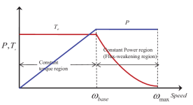
:flame: :flame: Field Weakening released! :flame: :flame:

FW allows VESC to go beyond base speed and will unlock the constant power range of the machine.
field weakening.png

[youtube]02jA0u5V-X0[/youtube]

Iq current in red
Id current in blue

More info in the pull request:
https://github.com/vedderb/vesc_tool/pull/34

The new control loops are enabled from VESC Tool:
field_weakening_vesc_tool.png

Use this with great care. With FW is super easy to blow a powerstage that don't have enough voltage rating, Axiom is certainly ready to take some abuse, but maybe small vesc clones not so much. It probably will take quite a while to get merged, but for those who would like to give it try can fetch the code from the PR.

MTPA is also included and ready for testers that wanna use the reluctance torque of an IPM machine, but they will need to set Lq and Ld inductances of the motor by hand because automatic parameter detection doesn't cover those new parameters.
 
Damn you guys are kicking ass! Field weakening has been a long time wanted feature for the VESC platform. Would you be able to tell us some of the downsides to field weakening besides the drop off of torque?
 
shaman said:
Damn you guys are kicking ass! Field weakening has been a long time wanted feature for the VESC platform. Would you be able to tell us some of the downsides to field weakening besides the drop off of torque?

You need to be carefull as you can run into a situation where the back EMF is greater then the CAP or power Transistor ratings.
But overall there is no downside really. With a perfect setup you will have a flat torque curve till you start to use field weakening then you will have a flat power curve. Its best to make sure all your normal cruising is done without field weakening and just use it for additional top speed. So with my CRX for instance with a full battery and no feild weakening top speed was 130km/h With field weakening was 210km/h I don't ever suggest pushing the limits like I do but I was successful with adding a LOT more top speed.
You don't notice the reduction in torque because its VERY gradual and its like a CVT transmission slowly shifting up as you gain speed. The efficiency loss is very small when done right as well.
 
About FW downsides, keep in mind that small VESC's have been historically low voltage devices, with 60V as an absolute maximum.
If at full modulation at 50V you are spinning the motor at 10000 rpm, if through FW you increase the speed to 12000rpm and somehow your pwm stops working (there are lots of reasons that could trigger this) your VESC will receive 60V from the motor and instantly blow up if the battery fuse trips.

So if your battery voltage is close to what your powerstage can deal with, you can't safely use the extra speed of FW. Typical case for vesc has been 50v max battery on a 60V powerstage.
Axiom has a larger voltage buffer (400V operation, 650V IGBTs), but you can easily use a 1200V IGBT and extend the constant power range.

Benjamin requested to be able to limit FW to non destructive speeds for his 60V hardware, I think we have a way to do so. We also need to add a couple of lines to avoid releasing the motor while FW is active, its important and we missed it.

Marcos do you have a compiled vesc tool with field weakening for linux?
No, you'd have to build it.
 
Correct me if I'm wrong, but if the pwm stops in FW mode and the BEMF becomes so high that the phase-to-phase voltage exceeds the battery voltage then the antiparallel diodes start to conduct at the sine wave peaks at an uncontrollable high current. Isn't it true?
If it is so, then the higher voltage IGBT wouldn't extend the safe FW speed range, because the diodes are in forward conduction. The phase-to-phase voltage is limited to Vbat+2*Vdiode by the battery and the diodes, and anything above that would be cut off at high current. In this case the safe FW operation would always be to limit the max possible phase-to-phase BEMF to the battery voltage (considering the failure mode that the pwm stops working).
 
peters said:
Correct me if I'm wrong, but if the pwm stops in FW mode and the BEMF becomes so high that the phase-to-phase voltage exceeds the battery voltage then the antiparallel diodes start to conduct at the sine wave peaks at an uncontrollable high current. Isn't it true?
If it is so, then the higher voltage IGBT wouldn't extend the safe FW speed range, because the diodes are in forward conduction. The phase-to-phase voltage is limited to Vbat+2*Vdiode by the battery and the diodes, and anything above that would be cut off at high current. In this case the safe FW operation would always be to limit the max possible phase-to-phase BEMF to the battery voltage (considering the failure mode that the pwm stops working).

It would be uncontrolled current yes. I had this happen once when running lebowski's brain board and I was deep into FW ~15,000 rpm with the leaf motor. I had a fully charged (other then the run I was in) battery and it did some harsh regen but I slammed on the brakes and saved it. Now in my case it was likely the IR of the wires and batteries limited the current to within the IGBTs ratings. But a battery with a lower C rating and or lower resistance wires would have likely been enough for my inverter to fail.

With Axiom we are working to ensure you never loose track of the motor and PWM never stops. But as we get there it would be advised to limit FW to keep back EMF no higher then the battery voltage.
 
Back
Top