Axiom: a 100kW+ motor controller

HighHopes said:
looking good so far. still need to add some insulation but this is a first fitup!


Hey, random question, what connectors are you using for the HV/High Amp connections to the battery/motor?

I've been struggling to find a connector capable of handling amps, waterproof and easy to use.
 
@mxlemming
ok, credit for actually doing the experiment. its possible that you do not see any difference because you are using low side shunts as these are referenced to DC negative and that's not going to help for high performance application because your motor is not such referenced (its floating). you need to measure phase voltage line-to-line and current measurement in line, for example using a fancy hall effect based current sensor with an aperture, like those made by LEM.

phase balance is pretty straight forward, nothing tricky. park clark uses all three elements, dq0 for example. that's one thing. here's another, when you measure 3 phases and just before you pass that to uC, do some quick math... sum all 3 together (obviously you'd normally get zero) and then add the summation to A measure, B measured, C measured and THEN pass ABC to uC. and the last thing, you need the motor to be under high dynamics, like aggressive acceleration. its more apparent with large motors because physically they have larger surface area on the windings and thus more leakage current (i.e. 50kW or more). i noticed improvement on a small 1kW motor but it was accelerating at a million degrees per second squared.

here's a question for you, if you're deep into VESC... why does VESC not use per units in the PID loop(s)?
 
jskounakis said:
Hey, random question, what connectors are you using for the HV/High Amp connections to the battery/motor?

amphenol
 
HighHopes said:
@mxlemming
ok, credit for actually doing the experiment. its possible that you do not see any difference because you are using low side shunts as these are referenced to DC negative and that's not going to help for high performance application because your motor is not such referenced (its floating). you need to measure phase voltage line-to-line and current measurement in line, for example using a fancy hall effect based current sensor with an aperture, like those made by LEM.

phase balance is pretty straight forward, nothing tricky. park clark uses all three elements, dq0 for example. that's one thing. here's another, when you measure 3 phases and just before you pass that to uC, do some quick math... sum all 3 together (obviously you'd normally get zero) and then add the summation to A measure, B measured, C measured and THEN pass ABC to uC. and the last thing, you need the motor to be under high dynamics, like aggressive acceleration. its more apparent with large motors because physically they have larger surface area on the windings and thus more leakage current (i.e. 50kW or more). i noticed improvement on a small 1kW motor but it was accelerating at a million degrees per second squared.

here's a question for you, if you're deep into VESC... why does VESC not use per units in the PID loop(s)?
Thanks for that. The situation is clearer now - critically this is an effect under acceleration. When I get some time I'll retry with high acceleration. I think I can replicate 1 million degrees/s², roughly that's 0 to 1000eHz in 0.4 seconds, basically 0 to the max speed I can run any of my larger motors in 0.4 seconds. Code to trigger and log this is not going to be entirely trivial though and it may well need an encoder to enable start from zero...

Have you replicated this on VESC/axiom? What was the hardware this algorithm was done with? I ask because there's a simple explanation if your hardware was operating with a single ADC and so does sequential adc readings. Under heavy acceleration, the back EMF is also changing rapidly and so the later sampled phase currents will be lower. Your phase balancing algorithm may well be effective in countering this effect. VESC samples with 3 separate ADCs so can get perfectly synchronised readings, also perfectly synchronised with the centre of V0. 20 years ago, such uC technology would have been far more primitive or rare/expensive... Still available with enough money and effort mind you, digital storage oscilloscopes were around then and clearly had the capability... But for example the dspic30 used on the Lebowski controller seems (at a cursory glance at the datasheet) to have 1adc and require sequential sampling.

Re. The VESC per unit in the PID loops... The current control loop https://github.com/vedderb/bldc/blob/c595d8ef9cf99962f1e81cb72c804bf4f90b078a/motor/mcpwm_foc.c#L3887
Uses units of volts and amps for the output and error, and kp and ki are precalculated based on inductance and resistance with units volts/amp and volts/amp second. This precalculation iirc is done in the VESC tool when you set up the motor.

The correction for bus voltage is done later on, with the circle limitation and duty later updated in the svm routine. It seems confusing as written, but it does seem to be rigourously done per unit... Am I understanding what you mean correctly?
 
i'm not the firmware guy on the team so i can't say for certain. but i worked on interpreting VESC to creat a block diagram of the PID loop from end to end and went into as much detai as i could and every time we were looking at PID stuff it was never in per units. like max PID is usually +1 and -1 this is what you should see but VESC did not have that, the max/min were looking like some sort of proportion to real values it was very strange. also, PID loops should have proper antiwindup but appears VESC does not have this, just has truncated version of it so we fixed this in our branch. but anyway, it just kills me to not work in per units, its so hard to debug when not in per unit.

20 years ago we used FPGA for motor control of that high speed stuff and the PID loop including dq/abc conversion was done in analog op-amps.

AXIOM uses three LEM hall-effect current sensors. its designed to fit either HASS or HTFS series. Its not the highest performing sensor but its bandwidth is more than enough for what a world record breaking EV can ever produce and more to the point this sensor allows for just 5V supply (we do not have +/-15V available for sensor). Phase A is measured on STM32 PC0, Phase B is measure on STM32 PC1, Phase C is measured on STM32 PC2
 
Ok, I searched and read through per unit https://en.m.wikipedia.org/wiki/Per-unit_system , it's a system for rating large motors and transformers on the 3 phase grid. I don't think it's really applicable to field oriented control, the solutions from ST, Infineon, TI... Don't use per unit either. To set gains etc on a wide range of motors and systems you kind of need to be working in SI units or an abstraction of them to be able to do things like the pole zero cancellation. I'm sure you could do it in per unit but there would be lots of translation forward and backward.

I'm now trying to work out how you implement a park transform with opamps. I guess it's "easy" enough if you have a sin cos output encoder and just lots and lots of summing opamps... But sounds like quite an achievement in its own right.
 
per unit inside the controller is 100% related. it doesn't matter if TI/Infineon do it or not. the concept of per unit is very very simple .. it translates in very simple way control parameters into a percentage. take the measured amps and divide it by the rated amps, that's it.. poof.. per units. why do this? its processor faster and a percentage is easier for a human to understand. so if told you the motor had 50 amps in it you would be like "is that a lot? i have no idea, what is the rating of the motor? its so hard to know what's going on without more info". now if i had said "the motor had 20% amps in it" you would be like "ok, your motor is cold.. there's LOTS of room to hit it with 5x as many amps". so there is an inherit intuitive feel for per units.

the other advantage is just a processing one. its simpler and faster to process the small number (i think its done in 2's compliment, but now i am stretching at a memory). i know, nobody cares...everyone laughs processors are so fast yudda yudda and then the next line they talk all smart about park/clarke conversion but don't realize that the ONLY reason park/clarke is done at all is to make processing simpler and faster too!!

so the two concepts just go together ... use per units inside the controller to make it simpler, faster, intuitive. rather than confusing (50amps.. is that too high for this motor?), slower (huge bit file), non-intuitive.

analog based PID is just super fast and zero software so has that appeal. of course it takes an extra day to tune the PID and better hope you never have to tune it to another motor... but in fixed motor application, its the simple cheapest and highest bandwidth solution there is. i think i did dq/abc with 3 -opamps and then PI current control with one op-amp.. so phase ABC was in total 6 op-amps if i remember. it wasn't FOC though, it was sine-PWM and there were some tricks to keep the DC offset from drifting (not obvious you need to do that and no application note will explain it for you). if you can keep the miliamps down you could do it in two quad-pack op-amps.
 
Quick comment on what mxlemming wrote about the ADC in the 30F... yes it has only one ADC but it has 4 samplers. So it samples the 3 voltages from the current sensors all at the exact same moment, and then does the ADC conversion on the sampled voltages one after the other. So the ADC readings the alhorithm works with are from the same moment in time.

This is actually the reason I chose the 30F (that plus it was a standard DIL)
 
Lebowski said:
Quick comment on what mxlemming wrote about the ADC in the 30F... yes it has only one ADC but it has 4 samplers. So it samples the 3 voltages from the current sensors all at the exact same moment, and then does the ADC conversion on the sampled voltages one after the other. So the ADC readings the alhorithm works with are from the same moment in time.

This is actually the reason I chose the 30F (that plus it was a standard DIL)

Yes, sorry I missed that while digging for explanations for this missing current. Quite a neat bit of ADC hardware I've not seen before. I dug out the reference manual and can see in your code:
https://github.com/casainho/Lebowski-controller-IC/blob/b3df66bc8eebb5f27621dd04f393ca69eaf84367/src/Lebowski_2A1/30F_powerstart_v2pA1.X/ADC.s#L29
You set the simultaneous sample bit.
Have you found this missing current on your travels? I had a quick go at recreating it, couldn't get anything conclusive. I've not spent a lot of time on it (maybe half an hour, on 2 occasions, just added a line of code that stores the highest running value of igamma) plan to have another go, but I will probably have to modify shunts to get higher resolution/lower noise to get any certainty.
 
HighHopes said:
analog based PID is just super fast and zero software so has that appeal. of course it takes an extra day to tune the PID and better hope you never have to tune it to another motor... but in fixed motor application, its the simple cheapest and highest bandwidth solution there is. i think i did dq/abc with 3 -opamps and then PI current control with one op-amp.. so phase ABC was in total 6 op-amps if i remember. it wasn't FOC though, it was sine-PWM and there were some tricks to keep the DC offset from drifting (not obvious you need to do that and no application note will explain it for you). if you can keep the miliamps down you could do it in two quad-pack op-amps.
HighHopes said:
@mxlemming
ok, credit for actually doing the experiment. its possible that you do not see any difference because you are using low side shunts as these are referenced to DC negative and that's not going to help for high performance application because your motor is not such referenced (its floating). you need to measure phase voltage line-to-line and current measurement in line, for example using a fancy hall effect based current sensor with an aperture, like those made by LEM.

phase balance is pretty straight forward, nothing tricky. park clark uses all three elements, dq0 for example. that's one thing. here's another, when you measure 3 phases and just before you pass that to uC, do some quick math... sum all 3 together (obviously you'd normally get zero) and then add the summation to A measure, B measured, C measured and THEN pass ABC to uC. and the last thing, you need the motor to be under high dynamics, like aggressive acceleration. its more apparent with large motors because physically they have larger surface area on the windings and thus more leakage current (i.e. 50kW or more). i noticed improvement on a small 1kW motor but it was accelerating at a million degrees per second squared.

https://github.com/davidmolony/MESC_Firmware/blob/96e373624d2c8158ae9f6a596646f43cff3bbeef/MESC_Common/Src/MESCfoc.c#L524
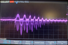
Is this correct? I have been testing this and have managed to get a motor accelerating at up to 576000erpm/s. I am limited by my power source. The accelleration is... violent? it basically goes from just slow enough to lock the observer on to max speed (290eHz) in 30ms. Any faster and it drops out my PSU and capacitor bank.
High accelleration rate current.png
I took loads and loads of these... Many caused trips of the PSU, many falsely triggered the scope, some started lower speed... This was just the last one before writing this up, nothing special about it, if anything it is one of the less good ones.
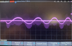
Here is another shot, after I finished the experiment and realised the ghost traces are because I had clipped the ground to one of the capacitor legs so the V0 current was offset against the V1...6 current. Resistance created by grabbing with hand.
Current cleaned up.png
Each div is 60A. Motor is 8080 esk8 motor with a pulley wheel on it, ~70kV 7PP; flux linkage=12mWb, Ld =~70uH, Lq=150uH... maybe... R=40mohm.
Low side shunts (hence the line at zero current) operating at 20kHz PWM, sampling in V0 only (obviously). MCU is F401, so the ADC is not actually synchronous(I think there is 0.8us between each of the triplet of samples), but the inductance is high enough I can see on the scope this is not significant.

So far, I have not found anything conclusive, but it does not make anything worse. Have tried both polarities of correction and also tried applying 1/3 the error as correction.

If correct, I will leave it merged as an option, in case someone drops my firmware onto a setup where it does make a difference.
 
I think you're doing it right except sounds like you're not using in-line (phase) current sensors? I think this matters because you need to measure the circulating current which I think won't happen when measuring leg currents.

VESC question for you ... does the MXLemming FOC observer make use of motor saliency in the algorthm?
 
HighHopes said:
I think you're doing it right except sounds like you're not using in-line (phase) current sensors? I think this matters because you need to measure the circulating current which I think won't happen when measuring leg currents.

VESC question for you ... does the MXLemming FOC observer make use of motor saliency in the algorthm?

The ADC is set up to sample at the dead center of "all low side MOSFETs on" so it is measuring the V0, freewheeling current. It's identical to the current measured by phase sensors at that exact time but obviously there's no smoothing and no filter integration of the transition effects or the effects in the V1 to V7 period.

I'm designing some phase sensor hardware at the moment (for GaN) so hopefully I can have another go some time around Christmas. On reflection, I wonder if what you've seen is the result of highly capacitive motors resonating with the wires which would be a much larger effect at high voltage and bigger motors.

The mxlemming FOC observer currently doesn't account for motor salience (neither does ortega, the salience in vesc is only used for HFI and MTPA). I (think I) know exactly how to code this, just 1) haven't got round to it and 2) I'm not actually sure whether it will help with anything. It's on my list of things to do. Do you have an application that particularly needs it?

The thing is, with outrunner motors, like most vesc applications and my ebike, the salience comes from the shell back iron being completely saturated thus the d axis has a low inductance. When you start pushing serious current info it though, you relink the flux into different magnetic circuits so the saturation pattern changes and therefore the inductance changes significantly. This becomes very apparent when fiddling with HFI algorithms.
 
now you're getting into on-line parameter estimation... ya, very nice. keep working on it :)

we have trouble sometimes with parameter detect when using IGBTs. sometimes its OK, works without a hitch and on other projects using IGBTs it doesn't work at all. i'm not sure if its because switching times are slower or deadtime is longer (or both). IGBTs are not common for low voltage application and/or low power but its very common for robust design requirement or high power.
 
The slow switching I'm unsure about, since I've never played with that, but the dead time i know is definitely a big problem when detecting inductance because it effectively becomes a voltage opposing the current. This is fairly manageable for resistance but for inductance measurement it's a right pain. It's not a problem at run time because the PID loops eliminate it (current doesn't change direction from the rotating frame perspective) but for high frequency injection it mutes the signal in a way that's not really compensable.

It also dramatically affects sensorless startup and observer locking. I made a compensator that works really well but unfortunately it managed to make FOC sound like BLDC so it won't catch on.

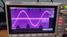
IMG_20220918_211216_694.jpg
Before deadtime compensation, curve is smooth but quite non sinusoidal

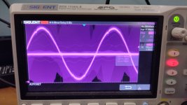
IMG_20220918_211359_433.jpg
After dead time compensation, the curve is much more sinusoidal but the remaining "dinks" have high frequency components that become quite loud.
 
one thing about deadtime compensation by software, it takes DC Bus utilization to do it. so you either slightly need a higher DC bus voltage than you actually need, or, don't expect to reach full torque (few % less). i have a patent in this area :wink:
 
HighHopes said:
one thing about deadtime compensation by software, it takes DC Bus utilization to do it. so you either slightly need a higher DC bus voltage than you actually need, or, don't expect to reach full torque (few % less). i have a patent in this area :wink:

https://patents.google.com/patent/US8760891B2/
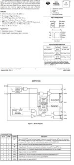
Interesting. Claim 1 Seems like a higher power, more comprehensive version and based on Vce rather than Vgs of:
Screenshot_20221111-163611.png
Which is an amazing little chip I used to drive my home made soldering iron. Wish there were 600V versions of it.

I found a way to detect the minimum dead time required using only the mcu. Hypothetically I could get it to run as a startup/calibration procedure or perhaps even at run time but ... That sounds like playing with fire. I use it as a test/diagnostic.


Re. The loss of torque... You mean speed I guess? And only relative to minimizing it physically... I'm fairly certain you don't lose anything by doing the compensation in software as compared to not doing it.
 
i've not seen that chip before, but yes i use Vce instead of Vge because the Vce voltage is where you see if its actually OFF, not the gate. The gate is the command, not the actual. In high power motor drives you can't afford a mistake, the stored energy in the DC link cap is so high a shoot-through is catastrophic. Also, my solution is isolated (as required in industry).

Re. The loss of torque... You mean speed I guess? And only relative to minimizing it physically... I'm fairly certain you don't lose anything by doing the compensation in software as compared to not doing it.

DC bus utilization shows up when mathematically derived it from first principles... but it can be seen simply like this, when software needs to increase the PWM a bit to compensate for the dead time it must have the head room always reserved to do that. this doesn't matter too much until you want to run at full power but can't because deadtime compensation by software always requires some PWM %. so that is the loss of torque.

What i wonder about.. maybe you gain the loss of torque back by re-shapping the inverter's phase current? if your deadtime compenstation makes the sinusoid shape better .. do you actually produce more torque? in theory yes because sinusoidal shape is better aligned with motor's bEMF (which we assume is perfectly sinusoidal). thoughts?
 
HighHopes said:
i've not seen that chip before, but yes i use Vce instead of Vge because the Vce voltage is where you see if its actually OFF, not the gate. The gate is the command, not the actual. In high power motor drives you can't afford a mistake, the stored energy in the DC link cap is so high a shoot-through is catastrophic. Also, my solution is isolated (as required in industry).

Re. The loss of torque... You mean speed I guess? And only relative to minimizing it physically... I'm fairly certain you don't lose anything by doing the compensation in software as compared to not doing it.

DC bus utilization shows up when mathematically derived it from first principles... but it can be seen simply like this, when software needs to increase the PWM a bit to compensate for the dead time it must have the head room always reserved to do that. this doesn't matter too much until you want to run at full power but can't because deadtime compensation by software always requires some PWM %. so that is the loss of torque.

What i wonder about.. maybe you gain the loss of torque back by re-shapping the inverter's phase current? if your deadtime compenstation makes the sinusoid shape better .. do you actually produce more torque? in theory yes because sinusoidal shape is better aligned with motor's bEMF (which we assume is perfectly sinusoidal). thoughts?

Dead time compensation in software doesn't detract atall from torque or speed of the equivalent system without, since without the compensation it is implicitly done by the current control loops, with the resulting non sinusoïdal shapes observed.

Nature integrates empirically. In this context, we can say it doesn't matter whether the voltage comes from the compensation or the PID or another mathematical construct, at the end of the day it's voltage pushing against inductance resistance and back EMF, we still need the same overall amount of it at the motor terminals to get the same performance.

I'm working on a method that eliminates dead time at the extremes of switching, so modulation can go up to 100% and the dead time no longer needs compensating out. All a bit pie in the sky and buzzing noises at the moment though, the actual implementation is always bitten by reality.

The sinusoïdalness of motors is something I've been thinking about a lot recently. The conundrum is that simplistically we would expect a non sinusoïdal waveform to work badly with FOC, which applies sinusoïdal waveforms. The observation though is that I have some remarkably non sinusoïdal motors with very low inductance (5th harmonic ~ 1/15th the amplitude of the fundamental) and it runs surprisingly well with very sinusoïdal current waveforms.
 
"I'm working on a method that eliminates dead time at the extremes of switching, so modulation can go up to 100%"
i have hard limit to avoid >98% and not lower than 2% (for example, actual % can be based on actual switch times). the reason is you don't want to get into a situation where a switch is ON for longer than the switching period (like 2 or 3 consecutive periods) and you don't want a small pulse, like 1%, that doesn't quite cause switch to reach saturation .. instead its in linear region. both situations cause switch overheat.

when i did hardware deadtime elimination, what i noticed was 5th harmonic increased. a lot. all other harmonics went down. i'm not sure what that is the case. 5th harmonic is a negative harmonic if i remember correctly.. dunno how that is related.

in theory the torque is produced when then current from the inverter is in phase with the voltage (bEMF) of the motor. its not a guarantee that the motor's bEMF is sinusoidal and its not a guarnatee the sinusoidal shape doesn't change through speed and/or load profile. i think it sort of stretches a lot due to saliency which is why i think MTPA works so good, it causes a stretch of the driven amps to match the motor. if there was a way to constantly monitor that, online parameter detection would be the basis for that, perhaps this could be explored further..
 
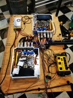
I'm really excited to test the integrated liquid cooled heatsink!
Also, seems latest version of VESC code works a lot better with motor parameter detection while using IGBTs. Cheers for that!

AXIOM_Rev2_benchtest_sm.jpg
 
Looks beautiful my friend. Make sure you put fresh humidity scavenger packs in just before sealing the lid. It's not uncommon for them to use up the first 70% of there sorbtive capacity in an hour or two of being inside a normal humidity room.

I also have seen some of the silica gel style beads saturate and wet out onto pcbs, and the gel is a weak electrolyte which leads to electrolysis driven failures.

I recommend molecular sieves sized for water vapor pore diameter.
This article has a nice set of reasons why.

https://www.impakcorporation.com/molecular-sieve-is-the-best-desiccant
 
liveforphysics said:
Looks beautiful my friend. Make sure you put fresh humidity scavenger packs in just before sealing the lid. It's not uncommon for them to use up the first 70% of there sorbtive capacity in an hour or two of being inside a normal humidity room.

I also have seen some of the silica gel style beads saturate and wet out onto pcbs, and the gel is a weak electrolyte which leads to electrolysis driven failures.

I recommend molecular sieves sized for water vapor pore diameter.
This article has a nice set of reasons why.

https://www.impakcorporation.com/molecular-sieve-is-the-best-desiccant
Thanks Luke.

I only left them laying in the controllers while they are not in USE. I have not decided what we want to do as a long term solution. Where I live relative humidity is common @99%. My shop stays ~ 40-50% But the Controllers will soon be outside under the hood and rear in the CRX. So with the vent that is IP rated I think humidity will still enter with heat cycles. I need to read the data sheet again. I wanted a Bellows... It looks ugly but would likely work well. Their is a good chance this will get potted for production...
 
Potting is #1 protection. A large enough bellows with molecular sieve packs is also a feasible option, but may require a maintenance interval to swap out the sieve pack for the humidity that migrates through polymer materials, like the bellows.
 
Back
Top