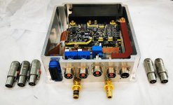
Axiom: a 100kW+ motor controller

larsb said:
Yes, question is how much effect this flatness has on thermal resistance? If it'd be double would the thermal resistance go up substantially?

This is 2 things, flatness and surface finish. Short answer is yes.
At some point the lack of surface flatness will start to leave a gap between the surfaces. Exaggerated it's like two bowls fitting together. The thermal paste has to work the heat across that gap.
Distortion from tightening modules could distort an otherwise flat surface depending on design and tightening torque.
Surface finish can be a bit odd. Roughness adds surface area but reduces direct contact area. If it's too smooth the thermal paste might not be able to fit and do its job. If it's too rough it leaves pockets / grooves of thermal paste for the heat to have to travel across. I'm sure it's semi-dependant on what thermal paste is used as well. You can probably find a white paper or a thermal paste manufacturer's surface finish recommendations. There's lots of bad info around this as well.
 
larsb said:
Sure, nothing new to me. I was looking for numbers.

Let's say you're using thermal paste with 4W/mK (pretty standard iirc) and you've got asperities leading to a 10um gap. This would be a near worst case for a 10um Rz, though the definition of Rz could allow for unlucky sampling or machinists to bend/stretch the tolerance. The bow on the igbt pack is intended to eliminate gaps due to thermal expansion, and also means the surfaces pull together tight.

So let's guesstimate that the conductive patch of the igbt is 110x57 looking at the datasheet. We then get
P=4W/mK *0.11*0.057/10*10E-6 =2500W/degC

The package is rated for 1800W dissipation (we all know that'll be brutally optimistic...) And the gap/thermal paste at this power would contribute less than 1 degree.

Installation is critical. Bubbles in the paste changes the 4W/mK to something more like 0.03W/mK. A big difference.

This is of course worst case analysis in terms of contact... The surface roughness is unlikely to result in a continuous gap but to have a saw tooth or similar shape, so the effective thickness of the thermal paste is less.
 
4 W/mK is pretty good for an electrically insulating thermal paste. A silver based one can get as high as 9 W/mK, but, no good if you're trying to keep things isolated.
 
jonescg said:
4 W/mK is pretty good for an electrically insulating thermal paste. A silver based one can get as high as 9 W/mK, but, no good if you're trying to keep things isolated.

Interestingly though the datasheet for the FF600R07ME4_B11 lists thermal grease with 1watt/mK.

The module itself has (and pretty much all have)2.5kV isolation. It also lists the thermal resistance as 0.04K/W, or 25W/K. Per igbt. There's 2 factors of 4 there (4igbts/diodes and lambda 4 vs lambda 1) but that's still somewhat off. I'm going to guess this is in part due to the area i presumed, and the resistance to lateral heat spreading.
 
looking good so far. still need to add some insulation but this is a first fitup!
 

Attachments

  • AXIOM_FirstFit2.jpg
    AXIOM_FirstFit2.jpg
    935.8 KB · Views: 1,666
The case looks fabulous, there are a lot things I would most definitely change:

1) Cooling lines coming in directly below the HV battery and phase leads, no no. Maybe entry from the right hand side.
2) Long snaking HV bus down the side past the control board, why? How about short and direct into the capacitor at the back of the case.
3) Control signals right next to high current phase outputs, sub-optimal I think. Short and direct from the left would be better.
4) Current sensors, direct straight shot off the IGBT pack via the current sensors and equidistant. I realize you can't do that having made the decision to have all the connections coming out the front. Food for thought.
 
kiwifiat said:
The case looks fabulous, there are a lot things I would most definitely change:

1) Cooling lines coming in directly below the HV battery and phase leads, no no. Maybe entry from the right hand side.
2) Long snaking HV bus down the side past the control board, why? How about short and direct into the capacitor at the back of the case.
3) Control signals right next to high current phase outputs, sub-optimal I think. Short and direct from the left would be better.
4) Current sensors, direct straight shot off the IGBT pack via the current sensors and equidistant. I realize you can't do that having made the decision to have all the connections coming out the front. Food for thought.

Keeping all the connections on a single face is probably the most universal configuration. All of your suggested changes stem from that design decision.

I think the packaging looks good. Lots of little details done right show that someone on the team knows what they're doing. Any reason the ampseal connector latch isn't facing the other way? Why not go for the powerlok gen 2 connectors? How is HVIL handled?
 
thepronghorn said:
Keeping all the connections on a single face is probably the most universal configuration. All of your suggested changes stem from that design decision.

Sure looking at any ebike controller. A cursory inspection of any traction inverter from any of the major OEM automotive manufacturers from the last three decades like Toyota, Honda, Ford, and GM would lead anyone to the completely opposite conclusion. The design teams from those companies all came to the same conclusion no doubt only after many design reviews.

I wonder if there is a compelling reason not to follow the same principals?
 
That really is looking rather premium. Love the yellow silk screen graphics :lol: The billet that was cut from must be about 600$ before machining. Each one of those powerlok connectors costs about the same as the entire controllers I usually build...

Is the box metal for emc purposes or just for premium ness? RIM moulding the top 3/4 would be much cheaper and have the advantage of insulating electrically. Also lighter.

For more premium ness can you replace the nasty crossheads that come with the connectors with hex bolts?
 
kiwifiat said:
thepronghorn said:
Keeping all the connections on a single face is probably the most universal configuration. All of your suggested changes stem from that design decision.

Sure looking at any ebike controller. A cursory inspection of any traction inverter from any of the major OEM automotive manufacturers from the last three decades like Toyota, Honda, Ford, and GM would lead anyone to the completely opposite conclusion. The design teams from those companies all came to the same conclusion no doubt only after many design reviews.

I wonder if there is a compelling reason not to follow the same principals?

The compelling reason is that they're building those inverters as an inverter/motor package, usually to set in a specific chassis. This is a universal inverter. As someone who's been messing with cars for a couple decades, I would agree that having all the connections on the same side is the most practical layout from a universal use standpoint.
 
kiwifiat said:
The case looks fabulous, there are a lot things I would most definitely change:

1) Cooling lines coming in directly below the HV battery and phase leads, no no. Maybe entry from the right hand side.
2) Long snaking HV bus down the side past the control board, why? How about short and direct into the capacitor at the back of the case.
3) Control signals right next to high current phase outputs, sub-optimal I think. Short and direct from the left would be better.
4) Current sensors, direct straight shot off the IGBT pack via the current sensors and equidistant. I realize you can't do that having made the decision to have all the connections coming out the front. Food for thought.


i think all these comments are fair. here are a couple of factors that made a big difference on why the connectors are grouped the way they are grouped. originally we had the water ports on the left side and the communication connector on that side too which eliminated need for a flex connector. but what our polling said was customers want all connectors on one side so we fought like mad to make that happen. if you saw the CAD file you'd see how hard that was to accomplish.

all connectors on one face makes it easier to mount and cheaper to build. the connectors are sealed so having water ports on same side is not an issue. if you spring a leak somehow , all the other connectors are sealed, but hey it really doesn't matter much if you're spraying water everywhere you're going to have a problem eventually anyway but with sealed connectors and sealed enclosure you have some time to resolve the issue. Same as if you drive through a puddle and splash water everywhere, you need sealed connectors.

the other issue, really need to keep the slab of aluminium within standard size width and height (it will be cut to random length). that's super tough to do. that took a few weeks to fine tune everything to a mm to get it all to fit. it as tough! keeping standard size keeps cost down.

at the end of the day you're not going to achieve perfection and please everyone. sub optimal to put comms connector 2" away from phase .. it would be 6" if connector were on the side. OK, but the question is 2" is that sufficient? if yes, then your comment is irrelevant and would just add cost and make mounting difficult for no value. you see? there are a lot of factors that go into everything we do and its just a matter of finding the right balance. we made our best effort in this first revision, test fit everything on a 3D printed version, we're happy so far. but is it the last version? probably not.. products grow and evolve.
 
the chassis is metal mostly because of heatsink cooling integration. the capacitor needs to be cooled too. its an added benefit that it reduces radiated emissions a lot.
 
"Any reason the ampseal connector latch isn't facing the other way?" part shortage. we need to order different part number for that one connector so the bussing comes through at the orientation required. would have been nice to have all bus same orientation but as it happens, that would require to grow the enclosure wider than standard dimension which adds cost. turns out you can buy all the same connector part number and just rotate it so the busing comes through at appropriate orientation. not ideal to the human eye, but fit/form/function acceptable. chip shortage is more than just chips... is everything.

by the way, $600 for enclosure .. no. maybe 5 years ago .. or maybe if you are building several hundred so paying upfront tooling cost on an automatic tool changer 6-axis machine is cost acceptable.. but otherwise costs are HUGE now for everything. the time on machine is the big cost, not the material. i designed this to have thickness of material where needed and remove everything else where not to make it light weight. that added cost because its more time on machine. i do not know what the savings would be if i just kept it heavy with less time on CNC. i might run that cost comparison some day but it is low on priority.
 
"any of the major OEM automotive manufacturers from the last three decades like Toyota, Honda, Ford, and GM would lead anyone to the completely opposite conclusion."

not anyone, just those who are not designers. major OEM have fixed designs and know exactly where the connectors need to be to minimize cost and they make their enclosures like that. optimized then then make thousands and thousands of them so its super cheap too, probably die cast. so they go and do that. it is totally different for us.
 
HighHopes said:
by the way, $600 for enclosure .. no. maybe 5 years ago .. or maybe if you are building several hundred so paying upfront tooling cost on an automatic tool changer 6-axis machine is cost acceptable.. but otherwise costs are HUGE now for everything. the time on machine is the big cost, not the material. i designed this to have thickness of material where needed and remove everything else where not to make it light weight. that added cost because its more time on machine. i do not know what the savings would be if i just kept it heavy with less time on CNC. i might run that cost comparison some day but it is low on priority.

600$ for the raw billet dude. I'd expect 3x that for as machined small volumes.

Inflation is indeed killing us right now, as well as shortages.
 
HighHopes said:
i think all these comments are fair. here are a couple of factors that made a big difference on why the connectors are grouped the way they are grouped. originally we had the water ports on the left side and the communication connector on that side too which eliminated need for a flex connector. but what our polling said was customers want all connectors on one side so we fought like mad to make that happen. if you saw the CAD file you'd see how hard that was to accomplish.

The customer is always right, more or less, so that is a perfect explanation. I can certainly see that you have gone to a lot of effort and I would expect expense to make that happen.

HighHopes said:
all connectors on one face makes it easier to mount and cheaper to build. the connectors are sealed so having water ports on same side is not an issue. if you spring a leak somehow , all the other connectors are sealed, but hey it really doesn't matter much if you're spraying water everywhere you're going to have a problem eventually anyway but with sealed connectors and sealed enclosure you have some time to resolve the issue. Same as if you drive through a puddle and splash water everywhere, you need sealed connectors.

Is it though? I struggle to see how running the HV power down the side of the case via those nice expensive looking copper bus bars would be cheaper than a shorter direct entry at the back of the case. Also a direct to PCB socket for the control signals like Sevcon uses would surely be cheaper.

I see your point about the water splashing around and the need for sealed connectors. The another issue I had in mind was legal liability.
If a reasonable person could foresee a situation where the HV cables and the cooling pipes were severed, lets say in a serious car accident, that leads to a hazard causing injury or death from electrocution then the designers may be liable if the courts agree the designers have not mitigated that risk when they could and should have. The critical legal test is "foreseeable". Is it foreseeable? That is a matter of opinion like all legal issues.
I don't think you need to be a rocket scientist to see that having all the connectors on one face increases the probability that multiple leads could be severed simultaneously whereas having them on opposite or even adjacent faces reduces the likelihood. It is a shame that customer demand has pushed you in that direction. I believe that liability issues is the real reason OEM automotive inverters do not have coolant pipes adjacent to HV cables.

HighHopes said:
at the end of the day you're not going to achieve perfection and please everyone. sub optimal to put comms connector 2" away from phase .. it would be 6" if connector were on the side. OK, but the question is 2" is that sufficient? if yes, then your comment is irrelevant and would just add cost and make mounting difficult for no value. you see? there are a lot of factors that go into everything we do and its just a matter of finding the right balance. we made our best effort in this first revision, test fit everything on a 3D printed version, we're happy so far. but is it the last version? probably not.. products grow and evolve.

I agree wholeheartedly that you will never please everyone, nor should you. I must say I am astounded that customers see utility in having all the connections on one face of the inverter when a device such as a traction inverter is likely to be installed once only and spend its entire life in one place.

My design process includes trying to minimize EMI as a high priority rather than having to mitigate it at a later stage. I don't accept that sufficient trumps "better" and therefor "better" is irrelevant. Having a direct socket to PCB connection like a Sevcon or a shorter cable entry certainly would not add cost to the product and would reduce EMI succeptibility and makes zero difference to the installation in a vehicle. In my opinion OEM inverters don't have control signals adjacent to phase leads due to EMI design rules and it has absolutely nothing to do with cost accountants or the idea that anybody who sees merit in how the OEM's do things are not "designers".

The great thing about open-source is that people from all over our planet can contribute ideas, I can't think of a single open-source project that I have personal experience with that has not gotten better with time.

I look forward to seeing Axiom evolve over time and wish the team every success.
 
kiwifiat said:
are not "designers".

I don't think you understand the level of work HH or the rest of our team has done and does on a daily basis.

All connectors are going to stay to one side. There is many reasons for this but the biggest is the ease of install.
One can argue that having things coming out on all sides of the enclosure cause the high voltage wires to be to close to the chassis of the vehicle and that is dangerous and someone should be sued... Imagine you have a fire wall and a fender this needs to be mounted against that leaves 2 sides to have connections then in most vehicles you will have something else this needs to be close to like the PDU or the motor. Sure you can sever both + and - and a coolant hose all at 1 time. Do you not think that kind of crash is already insane? I meen if you have this securely mounted under the hood of the car and something is able to cut both wires and at least 1 coolant hose you are in HUGE trouble like flew off the top of pikes peak and rolled down 3000 feet kind of trouble.
Also on that note I have some 90 deg BSPT fittings that screw into Axioms enclosure and can make both coolant hoses leave at a 90 deg to the connector surface and if the end user has a need for it to be that way then they can do it.

Copper is cheep. The set of laser cut buss bars is less cost then 1 of the Amphenol connectors! EMI is a non issue. We have tested this to great lengths and will continue to do so. But with the metal enclosure that is 100% needed for these power levels it is used for cooling and as a thermal mass and as a EMI shield. The Flex PCB is designed with EMI in mind and routed in a safe manner away from the phases and DC wires. The outer side of the coms has 2 shield GNDs for the exterior coms wires to have their shield. Also the connector surface is a spec'ed flatness surface which adds cost. That combined with having to rejig on the CNC to cut holes in multiple surfaces will 100% for sure add cost. Having the connectors all on 1 surface is for sure the cheapest option.

The customer did not push us to do it this way we put a crazy amount of work to make it that way for ease of use for the end user.

Sevcon is not a good example did you know Zero has to wrap the plastic cover with tinfoil tape to get it to pass EMI testing?

Also on that note just because you see someone do something a certain way doesn't meen its a good thing. MOST others will design for cost optimization as the number 1 goal and make an inferior product in the process. We tried to balance cost/quality/and performance as best as we could.

In the setup instructions it will be written with some warnings about external routing as well.

Truth is if we did things the way you think we should do we would have many others jumping down out throats to do it differently. You can have your opinions and use them for E-bike development but we are working on a product a few levels up from the industry you are working in.
 
Just want to chime in and say, I've been watching this project closely for years. I'm interested. And from what I can tell you've made outstanding design choices at every turn. Props! :bigthumb:
 
Arlo1 said:
I don't think you understand the level of work HH or the rest of our team has done and does on a daily basis.

You said something similar to mxlemming, I may be wrong but it seems that you are taking feedback personally when you shouldn't. There is a big difference between objective and subjective assessments and an objective assessment is rightly blind to who the architects of the design are and is only concern with the designs merits.

Arlo1 said:
The customer did not push us to do it this way we put a crazy amount of work to make it that way for ease of use for the end user.

I can only assume that you didn't read HighHopes response because he says " originally we had the water ports on the left side and the communication connector on that side too which eliminated need for a flex connector. but what our polling said was customers want all connectors on one side ..."

Arlo1 said:
Sevcon is not a good example did you know Zero has to wrap the plastic cover with tinfoil tape to get it to pass EMI testing?

Sure it is, almost a text book example. If I say:
1) the laws of physics tell us that the intensity of a EM wave decreases in accordance with the inverse square law, that is to say if I move twice the distance away from the source the intensity of the em wave is reduced to one quarter of what it was at the previous distance.
2) Faraday's law of induction tells us that among other things the amplitude of the emf induced in a conductor is proportional to conductor loop area and that loop area is plainly proportional to conductor length.
Then I can say that a reasonable design goal is to keep sensitive control signals away from noise sources and as short as possible. And that is precisely what you see in a Sevcon Gen4 and it is utterly irrelevant if the inverter case has a Faraday shield or not, the laws of physics do not change. But in any case you will see the same principles applied in any OEM inverters and certainly those from Honda, GM, Ford, and Nissan that I have torn down in my lab and also on plain display in the BMW i3 inverter in a very Sevcon manner.
Sevcon Gen4.PNG


Arlo1 said:
Also on that note just because you see someone do something a certain way doesn't meen its a good thing. MOST others will design for cost optimization as the number 1 goal and make an inferior product in the process. We tried to balance cost/quality/and performance as best as we could.

Agreed and note that that sentiment applies equally to everything your team does. I have only seen one design feature in any of the OEM inverters I have had in my lab that could not be explained by sound electrical engineering principals and that would be cost accountants cutting current sensor counts from three to two. Glad to see Axiom went with three current sensors. The Chevy Volt inverter has a short flex cable connecting control signals to the brain board of the controller, the engineers who design that inverter have a Faraday shield cast into the case right up to the point where the flex cable plugs into the main board, no sign of low cost engineering in sight in any of it's design features.

Arlo1 said:
You can have your opinions and use them for E-bike development but we are working on a product a few levels up from the industry you are working in.

There we are again, trying to blow out other candles by implying that nobody is qualified to comment on your design or works at your level does not make the Axiom candle burn any brighter. It does not matter if my name is "Bob the Builder" or James Clerk Maxwell we should be able to discuss Axioms design decisions on merit alone and drop the personal stuff. As it happens you are grossly misinformed.
 
What you need is a picture with a tape measure. LOL you show a picture of the Power-stage with the digital (control stage) on the side. But what you don't see is the digital stage is actually closer to the power stage then ours is. Axiom is simply a larger controller and there its not the same scale. I have a Stack of Sevcons here (like over 30 of them) and I have dealt with my share of issues with them.

I have done extensive testing with Axiom, So has the rest of the team. What we have works amazing. There is no need to move the Amp-seal connector it works amazing with 0 problems where it is.

You are trying to act like you think you are helping us. These decisions were made years ago and we chose all of them for VERY good reasons. Its not a help at this point to try to suggest doing things different.
 
I have only seen one design feature in any of the OEM inverters I have had in my lab that could not be explained by sound electrical engineering principals and that would be cost accountants cutting current sensor counts from three to two

ya this is pretty common. the text book says you can sum 2 of 3 measurements to zero and thus you don't need the 3rd sensor.. save money. they often miss that you need expensive op-amps because your window of time is much shorter with 2 sensors, but still probably an overall $ saving... cause good sensors are $$.

but here's the interesting part not mentioned in the text books (correct me if i'm wrong, cause i'd LOVE to read a text book on motor control theory that explains this better ).. if you are designing for high performance, which we are, you need 3 sensors because you need to regulate the zero-sequence current so as to squeeze out that extra juice. just to be clear, in a real system especially under extreme dynamics (not steadystate speed) the three sensors may not be balanced and may not even sum to zero (yes that's right, where did the current go if it did not flow to motor and return? huh?). short answer ... use 3 sensors, go after the peak performance, out perform other controllers that tried to save $50 on a $5000 BOM. 8)
 
HighHopes said:
I have only seen one design feature in any of the OEM inverters I have had in my lab that could not be explained by sound electrical engineering principals and that would be cost accountants cutting current sensor counts from three to two

ya this is pretty common. the text book says you can sum 2 of 3 measurements to zero and thus you don't need the 3rd sensor.. save money. they often miss that you need expensive op-amps because your window of time is much shorter with 2 sensors, but still probably an overall $ saving... cause good sensors are $$.

but here's the interesting part not mentioned in the text books (correct me if i'm wrong, cause i'd LOVE to read a text book on motor control theory that explains this better ).. if you are designing for high performance, which we are, you need 3 sensors because you need to regulate the zero-sequence current so as to squeeze out that extra juice. just to be clear, in a real system especially under extreme dynamics (not steadystate speed) the three sensors may not be balanced and may not even sum to zero (yes that's right, where did the current go if it did not flow to motor and return? huh?). short answer ... use 3 sensors, go after the peak performance, out perform other controllers that tried to save $50 on a $5000 BOM. 8)

The most concise explanation I've found is the infineon appnotes.

https://www.infineon.com/dgdl/Infineon-AP32370_PMSM_FOC_for_XMC1000-AN-v01_00-EN.pdf?fileId=5546d4625b3ca4ec015b3e42761006a8
In this one it explains the relevance of 3 shunts and selecting the correct two for optimal current measurement during the zero vector (that is when all three phases are low, and with phase sensors you can also read in the 7 vector, where all 3 are high). The VESC firmware your using uses a close variant of this, and I can therefore say definitively there is no further magic axiom is applying.

https://www.infineon.com/dgdl/Infineon-TLE987x-Sensorless-Field-Oriented-Control-ApplicationNotes-v01_00-EN.pdf?fileId=5546d46270c4f93e0170f23529817afa
In this one it explains the more budget single shunt method. The two low side shunt method is reliant on duty cycle limitation or control loop cycle skipping.

Neither are especially relevant to axiom since you are using phase inductive sensors which can read the current at any time, they are unaffected by the limitations of shunts, and there is no significant performance advantage to selecting any two, or to using all three. Inductive sensors are essentially immune to switching noise, behaving identically to an oscilloscope current clamp.

Kirchoff's law always holds true, the identity Ia+Ib+Ic=0 is true unless
1) you've suffered insulation failure in your wires or motor
2) you are wired in star and have inexplicably decided to return the centre to ground
It may appear falsely to not be true if
3) your sensors are saturated or broken.
4) you're using a 1990s ADC which is incapable of simultaneous or rapid sampling of multiple phases. (VESC uses a micro with a very good triple ADC)

The real benefit of 3 vs 2 inductive phase sensors is short circuit detection and shut down, where the un sensed phase would have been susceptible to shorts to ground.

This zero sequence (vector) control relates to the timing of the ADC measurements, and assumes (correctly) that the optimal way to read the currents is simultaneously in the exact middle on the pwm cycle (known as the zero or seven vector) where the current is in the exact middle of its decay cycle, and is therefore the linear average current. You could say it is synchronous.

The alternative is asynchronous reading, where you utilise phase shunts to take a reading at any time. This suffers from aliasing with the PWM and requires a lower current bandwidth. It is less applicable to low inductance motors due to the high variation in current at the pwm frequency.

You may also be conflating the zero sequence with the gamma term of the full clark (alpha beta gamma) transform which returns the DC offset. This is useable either as a detection of shorts to ground or as an indicator of the quality of your measurements. It is only applicable to 3 sensor systems.
 
Bob White told me once never make a presentation on a subject that's not in the book. he was right, but i do it anyway ;)

i would encourage you to try it. make the experiment on the same machine under the same conditions and take measure using a torque cell with two sensors and with three and try to make clever use of the full clark/parke transformation and phase balancing algorithm. i did this 20 years ago, it makes a noticeable difference so now that algorithm shows up in all my motor controllers.

there's actually quite a bit you can do with VESC, one thing we did a while back was add MTPA which also made a big difference on certain types of motors but before it was in the codebase it was in our R&D unit doing something special. another thing is launch control. prognosis health management including BIT which is along the same idea. but what we are working on the most is improving offline and online parameter estimation, i think there is room for VESC code improvement here especially for the large performance motors using the larger switching modules with their slower switching times. really the is a lot in firmware that can done.

you're right about improved fault protection with 3 of 3 sensors, forgot about that.
 
HighHopes said:
Bob White told me once never make a presentation on a subject that's not in the book. he was right, but i do it anyway ;)

i would encourage you to try it. make the experiment on the same machine under the same conditions and take measure using a torque cell with two sensors and with three and try to make clever use of the full clark/parke transformation and phase balancing algorithm. i did this 20 years ago, it makes a noticeable difference so now that algorithm shows up in all my motor controllers.

there's actually quite a bit you can do with VESC, one thing we did a while back was add MTPA which also made a big difference on certain types of motors but before it was in the codebase it was in our R&D unit doing something special. another thing is launch control. prognosis health management including BIT which is along the same idea. but what we are working on the most is improving offline and online parameter estimation, i think there is room for VESC code improvement here especially for the large performance motors using the larger switching modules with their slower switching times. really the is a lot in firmware that can done.

you're right about improved fault protection with 3 of 3 sensors, forgot about that.

Could you elaborate on the phase balancing algorithm? How does it work/how to implement? It isn't immediately clear to me how to do this or what to expect. I couldn't find any references to it online.

I tried a few experiments on my hardware a few days ago, and will try some more in the near future. I ran it with forced 3 sensor Clarke and forced 2 sensor Clarke. I am using low side shunts, so obviously at high modulation 2 sensor Clarke runs into problems, but running at a speed below that I was unable to find any significant difference in performance. The Clarke Igamma term remains pretty much at zero (allowing for ADC noise) just low single digit amps when feeding the motor ~50A phase implying good balance.

I am also starting to work on motor parameter estimation at runtime, it seems motors change a lot as they get pushed harder.
 
Back
Top