Axiom: a 100kW+ motor controller

HighHopes said:
Out of curiosity, how does Axiom get the cold plates specified for operation?
quick answer... we know the power dissipation and where that power is dissipated. we know the capability of the cold plate to reject heat when fluid has a certain flow rate and temperature. and poof.. just like that.

That's good to know too, but I can't figure out how to acquire one, as much as trying to specify one. It's not listed in the BOM on the Hackaday blog or anywhere else that I've been able to find.
 
personally, I start by figuring out the waste heat I need to dissipate in the worst case scenario. I usually solve this iteratively in excel, then multiply that times a safety margin. I usually assume ambient temp is around 40-50C to add some safety buffer, but this varies. If you have a spec to meet you use those conditions.

Conduction loss + switching loss (mJ dissipated during t_on+t_off * switching freq) + body diode losses from forward drop during dead time.
 
its listed in AXIOM datasheet
 
Arlin just passed 150kW at only 350Vdc, ~95% efficiency per motor drive. guess the new dyno coupler works :)

:bolt:
 
Is there a contact for the makers of this MC? Tried email and facebook but no reply.

I'd like to buy one or be involved in beta testing if they aren't yet available

Andy.
 
Is there a contact for the makers of this MC? Tried email and facebook but no reply.

hi Andy, i think its you i have been talking with by email but just incase its another "andy" and/or someone else has same questions.. in our message board signature is a link to a website that that has a "Contact Us" tab. its the most reliable way to get in contact because it goes to all of us and also it gets checked often.
 
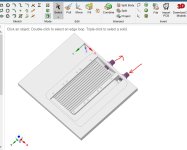
designing the enclosure with integrated cooling today. its not ideal because i'm dealing with constraints..
shown below is the bottom where the coolant flows (there will be a waterproof coverplate not shown). the otherside is where the IGBT modules sit, that side will have a flatness spec.

this is a work in progress, not finalized
 

Attachments

  • Heatsink1.JPG
    Heatsink1.JPG
    191.3 KB · Views: 2,363
I've been looking at the Axiom_Rev1_schematic.pdf and have a few questions:

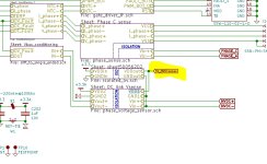
1) On page 12 of the pdf, sheet 0-650V phase voltage measurement using iso amp, where does
the AMC1301 get the isolated 5V power needed for the high side power supply VDD1?
I can't find VDD1 anywhere else in the schematic, the AMC1301 datasheet Fig.54 suggests
deriving it from the floating power supply of the upper gate driver but that won't
work for my application.
I was thinking of using an ADuM5010 isolated DC-DC converter to supply VDD1, this can source 30 mA.

2) Why did you choose an AMC1301 rather than an AMC1311 with a 0-2 V input range?

3) On page 1 of the pdf, the current sensors are single ended hall.
But they are fed into a differential input in the schematic, this
does not make sense to me. Are all the Lphase- inputs tied to GND?

Thanks for any info.
 
1. see block diagram on first page
2. i think the design started before AMC1311 existed. its hard to believe but i posted the original embodiment of this design i think back in 2012?? something like that. if i remember, my original design used differential op-amps in a special configuration to manage the high voltage "isolation". Ol'sk00l technique. Marcos when he redid the schematic to make use of STM32 processor instead also changed that interface and i think he used the fancy chip because its better, smaller and cheaper. but even at that time, the newer AMC1311 i think did not exist HVdc.JPG
3. the design was made to support both single ended and differential. there are some resistors that get populated or not or whatnot. we just sent instructions to a customer on how to do that... made me think we need write up a very descriptive appnote that explains in enough detail.

bye for now
 
HighHopes said:
designing the enclosure with integrated cooling today. its not ideal because i'm dealing with constraints..
shown below is the bottom where the coolant flows (there will be a waterproof coverplate not shown). the otherside is where the IGBT modules sit, that side will have a flatness spec.

this is a work in progress, not finalized

I'm sure you're aware, but unless you're casting that, the internal sharp corners on the ports are a no go.
 
i am not aware. my mechanical skillz are near 0.. i am making the first draft as best as i can before it goes to our mech expert for cleanup. feel free to give me more advice :)
 
Have you had any beta testers successfully integrate an Axiom board with unique inverter electronics? I've been messing with some hybrid vehicle inverters and getting my feet wet with Axiom for the price of the control board and some time learning to interface it to a Prius seems like a good and fun idea while I can't afford the whole inverter.
 
HighHopes said:
hi Andy, i think its you i have been talking with by email but just incase its another "andy" and/or someone else has same questions.. in our message board signature is a link to a website that that has a "Contact Us" tab. its the most reliable way to get in contact because it goes to all of us and also it gets checked often.

Yes, thank you for replying.
 
HighHopes: Thanks for the answers. For my current sensors I plan to use them single ended with the clever common mode chokes I found in the Makani controller design. I am told these have less than 1 A of noise with the controllers run at 1700V. I posted the schematic in the Makani teardown thread here: https://endless-sphere.com/forums/viewtopic.php?f=30&t=108154
 
Have you had any beta testers successfully integrate an Axiom board with unique inverter electronics?

ahh.. you're wondering if someone took the power electronics from typical EV. removed the brain board and inserted AXIOM? no, none of our customers have done this that i know of as they are all using their own motors in their own application (most are not even electric car application, HA!)

but really, this would be easy to do. the hard part is using the existing EV's electronics to generate the torque command and send that command to AXIOM. its hard because you need to decipher the communication protocol/messaging of existing system and then pipe it to AXIOM, probably via CANbus. its probably a lot of work reverse engineering existing EV's protocol.. but .. really, do you need to? tie the "gas" petal into AXIOM and you're done (maybe two analog signals or sometimes you can buy a gas peddle that has a CANbus output which can be be accepted by AXiOM). AXIOM will tell the IGBTs when to turn on/off. AXIOM needs current feedback but its design is versatile to allow quite a huge range (see recent posts in this forum). we have an appnote coming out that will explain this in exacting detail. so actually all that is fairly straight forward. i haven't tested too much any sensorless operation, mostly we use resolver. so your existing motor will have some sort of position sensor on it. hall sensor for super cheap motors, maybe sin/cos or resolver. AXIOM was designed to take a wide range of input so hopefully your motor will have something that works out of the box with AXIOM (or with minor changes) otherwise you'll have to buy a resolver and put it on the shaft of your motor and wire that back to AXIOM.

some day we may write a step by step.
 
HighHopes said:
i am not aware. my mechanical skillz are near 0.. i am making the first draft as best as i can before it goes to our mech expert for cleanup. feel free to give me more advice :)

Hey, shoot me a PM. I'm happy to help however I can!
 
I'm new to all of this but I have a few questions.

Can you use Axiom to control a 800v sensorless axial flux motor?

Is it possible to use SiC mosfets in parallel with the controller? Would this depend on the just the gate driver used?

Would the firmware need to be altered or would changing vesc settings be enough?

I'm trying to come up with the lightest possible solution for a UAV.
 
AXIOM was designed for 800V absolute max DC voltage (will require a 1200V rated cap which we are in the process of custom making but haven't actually received it yet). this means the applied voltage is lower because you have to leave room for transients and normal voltage overages and stuff. what exactly battery fully charge voltage then? you'll have to wait and see as we haven't fully characterized it at this higher voltage yet. don't hold your breath, it will be a while before we get around to that.

sensorless. theoretically it is possible because this algorithm is already in the VESC world and already working on other hardware but not really tested or validated with AXIOM yet. we used it a for a short period of time in the early days of testing and shortly there after moved to a resolver. we haven't gone back yet to fully flush out all the needs to get sensorless to work the way we want it. again.. don't hold your breath.

SiC mosfets, yes just depends on the gate driver.
 
Where can I purchase one of these motor controller for my EV project -

The battery pack is NOM 140 (100 to 150 )

Motor is BLDC outrunner - https://www.freerchobby.cc/products/mp240150-100kw-230kgthrust-outrunner-brushless-motor-for-big-plane-car-boat?pr_prod_strat=collection_fallback&pr_rec_pid=5282132852897&pr_ref_pid=5338086441121&pr_seq=uniform
 
Where can I purchase one of these motor controller for my EV project
Nowhere yet. We're still testing and validating. And I am still designing the enclosure. We work on AXIOM in between contract work which explains why its been a long time to fruition. But its coming :)

There's only one more technical hurdle and then to document all of performance and failsafe protections officially. The enclosure gets closer every day, I changed it to put all the connectors on ONE face rather than 2. Hopefully you'll like that (cause it was a lot of work hahaha).
 
Out of interest, what are people expecting these to cost when ready?

If I were to buy the two I need at the price suggested then it will cost over NZ$22,500 once taxes are paid. This is into the realm of professional OTS equipment and a good way into paying someone to design one. I'm not saying the price is too high, it isn't, but I'm wondering if that is what others are expecting
 
You don't need to pay someone to design one, we provided all the schematics and bill of materials (which means you can go part by part to see where the costs come from) so the design is already there for free. The IGBT, capacitors, bussing, enclosure, heatsink, connectors, sensors.. these things cost a lot more than the control board. The control board represents less than 10% of the overall cost I think so probably not worth your while to pay someone fat stack of cash for that effort unless you have some other reason than trying to save money.
 
TrifiveEV said:
Out of interest, what are people expecting these to cost when ready?
Well you can start with the cost of the parts and its going to be more then that. We are not talking about selling a kit or a control board.
If I were to buy the two I need at the price suggested then it will cost over NZ$22,500 once taxes are paid. This is into the realm of professional OTS equipment and a good way into paying someone to design one.

As it should be. The team is not a group of back yard hillbillies. Now having said that I know we can spend some time making more professional videos which we will soon enough. Covid has limited my ability to make things look more pleasant.
But at the end of the day this is a top notch product!
 
Back
Top