Kepler
10 MW
As this is the M600 dedicated thread I have added my partial tear down notes and video.
Completed the partial strip down of the drive so as to inspect the gears and check the level of lubrication.
The drive came apart quite easily with no special tricks needed.
I can confirm the drive has metal gears throughout. The intermediate gears certainly could have done with more lubrication however it certainly wasn't dry. The final drive gears looked to be lubricated adequately.
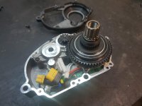
This first picture shows the speed controller. A really neat compact unit. Not potted though so water ingress could be an issue. That being said, there is a nice fitting gasket on the cover. Worth noting this drive doesn't look like it uses traditional hall sensors. Instead it has a single magnet on the end of the motor pinion gear which is located behind the shinny circular post just behind the 3 phase plug. This means you will need to take care refitting the speed controller cover as I presume there is a sensor on the speed controller circuit board that picks up a pulse from this magnet.
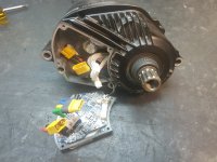
Yo can see the final reduction gear in this picture. Looks to be well lubricated. The bearing setup looks to be well engineered.
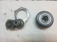
On the left is the secondary gear reduction. The gear on the far left is the steel gear that replaced the original nylon gear.
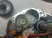
This picture shows the cavity which the intermediate gear reduction fits into. Looks like you could pack a good amount of grease on the intermediate gears without the issue of grease spilling out. You can also see the magnet on the end of the motor pinion used to sense rotation.
[youtube]muSNIUXNNaQ[/youtube]
Completed the partial strip down of the drive so as to inspect the gears and check the level of lubrication.
The drive came apart quite easily with no special tricks needed.
I can confirm the drive has metal gears throughout. The intermediate gears certainly could have done with more lubrication however it certainly wasn't dry. The final drive gears looked to be lubricated adequately.
This first picture shows the speed controller. A really neat compact unit. Not potted though so water ingress could be an issue. That being said, there is a nice fitting gasket on the cover. Worth noting this drive doesn't look like it uses traditional hall sensors. Instead it has a single magnet on the end of the motor pinion gear which is located behind the shinny circular post just behind the 3 phase plug. This means you will need to take care refitting the speed controller cover as I presume there is a sensor on the speed controller circuit board that picks up a pulse from this magnet.

Yo can see the final reduction gear in this picture. Looks to be well lubricated. The bearing setup looks to be well engineered.

On the left is the secondary gear reduction. The gear on the far left is the steel gear that replaced the original nylon gear.

This picture shows the cavity which the intermediate gear reduction fits into. Looks like you could pack a good amount of grease on the intermediate gears without the issue of grease spilling out. You can also see the magnet on the end of the motor pinion used to sense rotation.

[youtube]muSNIUXNNaQ[/youtube]


