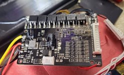
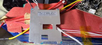
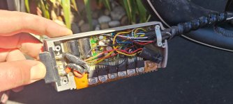
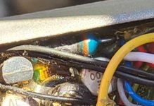
Hello, what I see in the pictures is a cracked mosfet. As for mosfet failures things like shorted motor phase wires blow them up.
You might be thinking of controller FETs--those are what are typically blown up by motor wiring issues, since they are directly connected to them.
The BMS FETs *could* be blown by that, too, but normally only if the controller is first destroyed by also having blown FETs allowing a direct short across a phase bridge from battery positive to battery negative.
Either of those is fairly easy to test for just by turning the motor backwards by hand--if it has a lot of resistance to turning compared to normal, or is simply very hard to turn, then either the motor wiring itself or the controller FETs are shorted.
But something caused the BMS to fail. THere are quite a few things that could do this, and some of them are cascades of little things that lead to big problems; I only cover a couple below:
Typically the FETs are undersized or exactly sized (for current *and* voltage) in these (and controllers, etc) so that they can just barely handle the load they are "rated" for, instead of sizing them for a significant overload factor (25-50% or more), because it costs more to do that.
So a common problem is that being run near or at (or beyond) their limits, they create a lot of heat, and mostly being inside the heatshrink of the battery right up against the cells, which also generate heat, and inside a battery casing or bag, which prevents exit of that heat, they can overheat and fail, or age faster due to the heat and eventually fail, etc.
They can also get voltage spikes every time the BMS has to shutdown due to cell LVC (low battery), if the system depends on the BMS to protect the pack, or if the pack has a cell-level problem (often visible as unbalanced cell voltages). These spikes can exceed the FET voltage ratings, and blow them up like you see.
Usually when the FETs fail, they fail shorted (and silently/invisibly), so that you still get current flow thru them as if they were still on; if only one FET fails this way but the others in parallel don't, that one FET is now taking all the current and may explode like you see. Then the rest of the FETs keep the pack shut off, so you only see leakage voltage on the output when not connected to anything (and when it's plugged into the controller usually you don't see any voltage).
So....if you get a new BMS, I'd recommend a current capability rating higher than the controller's current limit (so the FETs aren't stressed), but a BMS current limit / shutdown protection the same as the previous one (to keep protecting the cells against over current).
Also using a BMS with FETs rated for much higher voltage than your system will ever see, may help prevent failures from voltage spikes.
Unfortunately it may be difficult to get enough information about any particular BMS to do these things, except with the programmable / bluetooth BMSs where you can buy one capable of more cells than you need it for, and more current than you need it for, and then just turn it all down in the software, and wire it up to just the cells you need. Disadvantage to these is that they are more complex and have more chance of bugs and unpredictable types of problems.
Unfortunately I don't have direct experience with any of the good BMSs to tell you which ones those might be (just bad ones, and old good ones that aren't made anymore).


