Battery Testing Data - Reports from the Road

AndyH

10 kW
Joined
Jun 9, 2008
Messages
547
Location
San Antonio, TX, USA
This is a response to an excellent suggestion by Adam/Ahambone in another thread.

While there are other threads where single cells are examined, maybe this can become a somewhat central place to put pack performance data. This might give us a pool of data to compare/contrast different battery types, BMS types, chargers, and management strategies -- and see how they work (or not...) 'in the real world'.

So - warm up your dataloggers and bring on the info!

Andy
 
Tag - I'm it.

We know that we can change a single cell with a power supply or other single cell charger and if the charger is set to 3.65V that cell will completely fill and finish the charge at 3.65V every time.
View attachment LiFePO4_Curve.jpg
We know that once the cell voltage starts to rise near the end of charge (say, 80 or 90% state of charge [SoC]) that if we keep adding energy the voltage will quickly climb up the chart. We also know that if we add more energy while the cell is in the flatter part of the curve (like 60% SoC) that we won't see that voltage rise.

But what happens to cells charged in a string?

Here's the first 20 minutes of a charge for a 60Ah pack of 21 cells. There is no BMS installed - we'll look at what happens to a 'naked' pack during charge.
View attachment First_20min.jpg
The vertical green lines are five minutes; the green 'ticks' on the bottom are 1 minute. As one can see on top - this is a 3-3.7V range. The pink line is charge current.

At the 3 minute mark we're looking at the uncharged pack. Cell voltages range from 3.25V thru 3.34V.
At the 5 minute mark we have 13A in from the charger. This part of the charge is pretty boring to watch.

Let's speed this up a bit.
View attachment First_105min.jpg
All right. Now we can see a lot more of the 'LiFePO4 Charge Curve' here. We can see that some of the cells have 'turned the corner' in the charge curve and are nearly full. Along the right we can read that cell 18 is done at 3.67V and that the top 10 cells are all at 3.60V or above.

Not all the cells have 'turned the corner' though and are soaking up as much fo the 13A charge they can get.

Then it gets interesting. Let's zoom in on the last 5 minutes we can see:
View attachment MIn100-105.jpg
Here's a better look at cell voltages when under charge. The voltage and charge current numbers on the right are from the far right of the chart. Seven of the cells - 1/3 of the pack - is at or below 3.55V -- and the pack is still getting a full 13A of charge current. This is about to change, though. Stay tuned for part two...
 
Our charger is a Thunder Sky TSL60-15. It's a 'too smart' charger designed to mimic a CC/CV charge curve overall, but it will adjust charge rates based on pack voltage. At the end of the traditional CV phase it starts to 'pulse' to balance the cells. The 'pulses' are quite slow - on for 2 minutes pushing somewhere between 1.4 and 2A, then off for 18 minutes. Here's the curve from Thunder Sky:
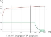
TSL_Charge_Curve.jpg
Here's how the charger actually stepped the current down after the 'pack average voltage' peaked:
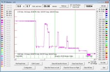
Charger_Input.jpg
This isn't the typical CV phase where current gently decays, is it?

But what happens to cell voltages as the charger 'slows down'? Here's the pack during the above charger 'step-down':
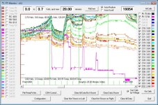
20min_after_peak.jpg
Wuh-oh. Where did our cells go? Yeah - off the charts. Let's adjust the scale a bit and see what happened.
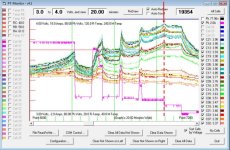
CV_step_down.jpg
At the peak, our top cell hit about 3.96V. [edit] Keep in mind that this charger is set for 3.62V per cell - yet cells are pushed well above that... [/edit]

Look at the cells left from the red arrow to the next voltage 'peak'. The full cells were being pushed up with a 2A charge, but the lower cells were still staying 'flat' - they were still soaking up as much energy as they could. These might be our higher capacity cells. They might also be the cells that started the day at a lower SoC. We don't know why they're not fully charged, but we know they're not done yet. Unfortunately for them, the charger's done. They won't be fully charged this time around.

Cell voltage will drop as the cell sits after a charge. The A123 cylindrical cells will hold a surface charge until it's damaged, but most other cells will not hold a surface charge and will bleed down once the charger is disconnected.

Remember in the last section when we looked at the charge curve? We saw that a full cell will have a voltage jump when hit with a charger, but a not-quite-fully-charged cell won't.

Let's look at the voltage decay and the effect from the first 2A for 2 minutes pulse from the charger:
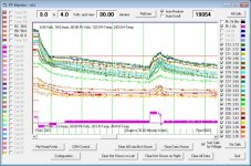
First_Pulse.jpg
Just before the pulse our lowest cell was at 3.33V and the bottom six cells are below 3.40V. At the peak near the end of the pulse our high cell hit 3.73V. This was only a 1.2A pulse.

Let's look at the effects of nearly four hours of 'pulse and glide' mode on the pack. Do these pulses give us enough energy to bring our stragglers up?
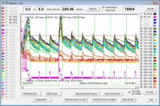
Pulse-N-Glide.jpg
I'm thinking the answer is 'NO' here...

The charger hit the pack with a quick 13A on pulse three. It pushed our high cell up to 3.98V but our stragglers stayed in the mid-3.x range.

Clearly the 'Naked' pack has nothing to keep cells from being pushed over my 3.7V comfort zone (the horizontal red line in the charts). And there's nothing here to help the low cells get topped.

When I step into the garage after this charge, I see a pack voltage in the low 70s, the charger is off. Everything looks good - let's go ride! One thing I don't know by looking at the gauges next morning is that I had cells pushed to nearly 4v overnight. Another thing I don't know is that 1/3 of my pack isn't fully charged. This will likely shorten my ride. And because I'm relying on the controller's low-voltage cut-off of 52.5V (2.5V per cell average), my low cells might not be very happy at the end of the day...

Andy
 
Would the CBA put out this kind of graph? I did not know that it could monitor a charging sequence like this.

I think that in the morning, I could do a simple version of this test by checking all cell voltages correct? Kind of a drag for 100 cells or so, but for testing purposes, not that big a deal.

How does your machine monitor all the cells being charged? Does it have a connection for each cell?

I found this very enlightening, thank you.

Katou
 
I'm glad Katou! Thank you!

Here's the back-story on the cells and monitoring. The short answer is that I'm using a PakTrakr display, three 8-cell sensors and an inductive current sensor to capture the data. Raw data from the remotes is transferred into a custom display program. The CellLog units can collect dynamic cell data; there are probably other solutions as well.

The CBA can collect this type of data for a single cell up to about a 15S pack - I believe it's got a 48V max voltage (CBA II - the CBA III might be higher). The new software has a 'charge monitor' mode that allows collection.

Andy
 
Outstanding data Andy!

Thank you for shareing this with us.

I don't think I've ever seen anything more clearly showing the importance of a BMS.
 
I'm charging my pack, 4 cells at a time and I've never seen a voltage over 3.76 so far. I sat there with it a few times while it's charging and monitored each cell. I think if you charge 12 to 16 cells at a time, it's bad like you said but if you do it 4 cells or less at a time, it might be okay.
 
Is it not true the pack is basically charged to the lowest energy cell in the TS charger scheme. Since the cell that stores the lowest amount of energy reaches the highest voltage first, if you stop when the first cell reaches 3.7 (your comfort zone) then all the cells took about the same amount of energy. It may be true that there are cells that can take more, but why bother when you ride ends when the lowest energy cell is drained what the state of the higher energy cells are is irrelevant since the lowest energy cell ends the ride and defines your range.

This is my theory based on my experience with TS cells, not trying to start a flame war in any way I just wanted to state my experience with TS cells

edit: I'll even make the claim voltage is a second order effect, energy in and energy out and the capacity of the cell to store energy is what matters. We could start another thread on what defines energy into and out of a cell but its not voltage

Mark
 
Very glad you started this thread Andy... and very nicely described and illustrated too. 8)

What you are exhibiting here matches spot on with my recent observations. Luckily, I am only dealing with 8s. I have been using and experimenting with a CBAII, CellLog8, iCharger 208b, a bulk LiFePO4 charger, and even a 24v CC/CV SLA charger (2.5 amp).... Headway 10ah cells BTW.

Well guess what, I totally abandoned the SLA charger with its 30 volt CV phase... I freaked out when I saw the 4+ voltages on my more "filled up" cells and figured that was not a good thing :oops: Too bad :? , since it was so nicely integrated with the controller on my EV :cry: .

Looking forward to participating and learning more with you all here :mrgreen:
 
markcycle said:
Is it not true the pack is basically charged to the lowest energy cell in the TS charger scheme. Since the cell that stores the lowest amount of energy reaches the highest voltage first, if you stop when the first cell reaches 3.7 (your comfort zone) then all the cells took about the same amount of energy. It may be true that there are cells that can take more, but why bother when you ride ends when the lowest energy cell is drained what the state of the higher energy cells are is irrelevant since the lowest energy cell ends the ride and defines your range.

I appreciate your thoughts here, Mark. I understand that the overall ride will be limited by the lowest capacity cell.

But this first 'examination' is to look at what a 'naked pack' actually does when it's charged and discharged. No assumptions, no 'in a perfect world it should...', no guessing. It's my position that one cannot decide if management is necessary until they know what's 'really happening'.

(As an aside - there's more to the story with this pack than simply cell capacity. Do you know what it is?)
 
I'll venture a guess :mrgreen: Is it a bad connection in the string?

BTW, One of my cells (in a paralleled pair) had a significantly lower voltage (when I was test discharging it at 25 amps on the CBA. I am swapping it out for one of my spare cells and will evaluate to see if it helps alleviate my runt syndrome on the #4 position.

I am having fun :p
 
My pack behaves very much like your pack maybe all TS packs behave this way.

What I have done is one more test after a charge cycle such as yours I took the lowest voltage cell and put it on a single cell charger and monitored how many Amp/Hr more I could put into that cell. This gives me data as to the level of unbalance or the delta in cell capacity in my pack.

What I found with my 40AH cells is that the delta is at most 1AH from what is the weakest cell to the cell capable of holding the most energy.

Edit: Would be interesting to see how the pack behaves witout a bad connection

Mark
 
AndyH said:
markcycle said:
Edit: Would be interesting to see how the pack behaves witout a bad connection
Mark

Why do you think there's a bad connection?

Oh I 'm sorry I misread forgive

Mark
 
markcycle said:
Is it not true the pack is basically charged to the lowest energy cell in the TS charger scheme. Since the cell that stores the lowest amount of energy reaches the highest voltage first, if you stop when the first cell reaches 3.7 (your comfort zone) then all the cells took about the same amount of energy. It may be true that there are cells that can take more, but why bother when you ride ends when the lowest energy cell is drained what the state of the higher energy cells are is irrelevant since the lowest energy cell ends the ride and defines your range.

This is my theory based on my experience with TS cells, not trying to start a flame war in any way I just wanted to state my experience with TS cells

edit: I'll even make the claim voltage is a second order effect, energy in and energy out and the capacity of the cell to store energy is what matters. We could start another thread on what defines energy into and out of a cell but its not voltage

Mark

The charger doesn't know what any one cell is doing - it's working with pack voltage. I didn't stop the charge at 3.7 - I only logged the data.

What I think I understand from watching this charger over the last year with and without BMS devices is that the charger's programming seems to do a pretty good job when the cells are in fairly close top balance. It also appears that if a few cells get out of balance the gap widens over time rather than narrowing.

voltage as second order...I'll buy that!

But...if one is charging only with a bulk charger, and limiting the ride with either a conservative Ah number (or a pack-average controller low voltage cut), how does one keep individual cell voltages in check?
 
AndyH said:
markcycle said:
Is it not true the pack is basically charged to the lowest energy cell in the TS charger scheme. Since the cell that stores the lowest amount of energy reaches the highest voltage first, if you stop when the first cell reaches 3.7 (your comfort zone) then all the cells took about the same amount of energy. It may be true that there are cells that can take more, but why bother when you ride ends when the lowest energy cell is drained what the state of the higher energy cells are is irrelevant since the lowest energy cell ends the ride and defines your range.

This is my theory based on my experience with TS cells, not trying to start a flame war in any way I just wanted to state my experience with TS cells

edit: I'll even make the claim voltage is a second order effect, energy in and energy out and the capacity of the cell to store energy is what matters. We could start another thread on what defines energy into and out of a cell but its not voltage

Mark

The charger doesn't know what any one cell is doing - it's working with pack voltage. I didn't stop the charge at 3.7 - I only logged the data.

What I think I understand from watching this charger over the last year with and without BMS devices is that the charger's programming seems to do a pretty good job when the cells are in fairly close top balance. It also appears that if a few cells get out of balance the gap widens over time rather than narrowing.

voltage as second order...I'll buy that!

But...if one is charging only with a bulk charger, and limiting the ride with either a conservative Ah number (or a pack-average controller low voltage cut), how does one keep individual cell voltages in check?

I don't believe one can have all the cells at the same voltage at the end of a charge cycle and have the cells be at the same energy state at the pack's drained state, I claim at the pack's full state, it is OK for the voltages to deviate ( within the manufactures specs.)

Pack average controller LVC is dangerous and doesn't work
A combination of cell LVC and Watt-Hr used is the correct pack monitoring for safe battery pack use.

Mark
 
I removed a cell group from my 16-cell 10Ah LiFePO4 pack that went bad and now have a 15 series pack. I also removed the BMS and have put 9 cycles on it so far in this configuration. Before the first ride I balanced the voltage in each cell to 3.60V then simply rode and charged it back to 54.3V (avg 3.62V/cell). For the first 6 cycles I dutifully measured the individual cell voltages after a ride and then again after charging, I did not re-balance the cells each time.

Here is the range of the cell voltages after each ride;

Ride 1: 5.74Ah used

5 cells @ 3.30V
10 cells @ 3.29V

Ride 2: 7.64Ah used

1 cell @ 3.28V
10 cells @ 3.27V
3 cells @ 3.26V
1 cell @ 3.25V (#11)

Ride 3: 7.79Ah used

7 cells @ 3.27V
6 cells @ 3.26V
2 cells @ 3.24V

Ride 4: 7.71Ah used

7 cells @ 3.27V
7 cells @ 3.26V
1 cell @ 3.24V (#11)

Ride 5: 8.69Ah used

2 cells @ 3.25V
8 cells @ 3.24V
4 cells @ 3.23V
1 cell @ 3.20V (yup #11)

Ride 6: 7.82Ah used

1 cell @3.30V
8 cells @ 3.29V
4 cells @3.28V
1 cell @ 3.27V
1 cell @3.26V (#11)


After subsequent rides I simply did a quick check of cell #11. The voltages after charging show a much wider spread, up to 0.15V difference, however that represents a tiny difference in capacity. When you think about it balancing the voltages of the pack at the end of a charge is accomplishing very little if anything.

-R
 
Balancing Required?
If one never balances the cells, it is possible to have the cell "spread" widen. At least occasional Monitoring is essential to identify "weak" or "bad" cells.

Cell Damage:
Some effective mechanism to avoid over-charging, and to avoid over-discharging of individual cells is absolutely necessary to avoid cell damage and achieve longer cell life.

Monitoting Cells:
Large differences in SOC (10% to 30%) will typically show up as only tiny voltage changes (0.01 volt or so) in the LiFePO4 mid-discharge range (3.2 to 3.3 volts or so), so mid-capacity monitoring tells us very little that is truely useful.

Center Balancing:
Doing "center-balancing" by voltage is essentially impossible.

Low-End Balancing:
Since the cells do not often get down to their low end (under 3.0 volts), balancing at the low end is at best infrequent. If one attempts to implement low-end balancing, it either requires charging only the low cells, or discharging the higher ones (or both). Not "easy" to implement, though not impossible. But, still, probably too infrequent to be really useful.

High-End Balancing:
With an opportunity to do "balancing" at each charging, it is relatively easy and inexpensive to implement. Best when cell monitoring can detect high cells and reduce the charging current to a low value that can be "handled" at the cell level. A simple 1 to 2 amp shunt is an "easy" way to handle the "excess" (but LOW) current at the cell level.

The Charger:
Essential is a "charger" that can be "throttled back" in some way when the "top" cells are getting near the "too high" SOC (or voltage). The too-high voltage is easy to detect at the high end of SOC. High-cell detection and a simple mod to add an input to "turn down" a power supply's current-limit value would typically do the job nicely.

How Often:
With well-monitored cells, balancing should only be required occasionally. Detection of impending individual-cell "failure" is strongly desired, before further cells are compromised.

Summary:
Monitor each cell (at least occasionally), and implement some form of over-charge and over-discharge protection.

AndyH's graphs show what starts to happen at the high (charging) end. Note: The High-Low cycles during the high-current charging (and the transition down to "pulse-and-glide" charging) are part of the "smart" charger's attempt to measure what the pack is doing when NOT at full charge.

Some similar while-riding graphs of low-end cell voltages will also be very instructive.

Thanks, Andy
 
markcycle said:
AndyH said:
markcycle said:
Edit: Would be interesting to see how the pack behaves witout a bad connection
Mark

Why do you think there's a bad connection?

Oh I 'm sorry I misread forgive

Mark
Sorry that was just me that started that nonsense. I am very inexperienced at this stuff :oops:

The reason was this: Wasn't clear on Andy's particular cell arrangement with that large pack. i assumed it was probably a combination of parallel and serial connections. I noticed in the graph what seemed like two primary groupings of cells in regards to how they were topping off.

I actually had a connection problem early on in my first pack. It involved a parallel pair where one of the cells had a poor connection and the amount of actual current passing through each cell seemed to be different, with the loosely connected cell lagging during discharge, leaving the other cell taking the brunt of the current (hence energy) draw. It was hard for me to diagnose but I eventually found it. After that, my CellLog displayed discharge readings for the pair that better matched the other pairs in the string.

I thought because of Andy's relatively high current charge rate that something similar might be going on... but like I suggested above, I am just newbee student with all this stuff now :roll:
 
Mark and Scoot - no need to apologize or get stressed about loose connections - I was just asking a question - not pointing fingers. :)

Scoot - Excellent point about possibly loose connections with parallel cells. My datalogging so far has been with 1P packs - I don't know what a loose connection would 'look like'. THANK YOU!
 
Hey Gary! Good to have a sanity check from Doc EE. :) (Gary's the author of the PT Monitor software, BTW.)

I logged some data for a straight CC/CV charge yesterday but grabbed the wrong Zaurus...one stops capturing data when the screen saver kicks in, the other doesn't. I only got the first 1/2 of the charge and completely missed the balancing phase. :(

I'm hoping to get a look at charging with a power supply and 'naked pack', then look at shunts only, then shunts and charge control (AKA Goodrum/Fechter BMS). I also want to get some good logging from pack-level LVC (controller only), then throttle-pull-down, then the brake inhibit. I hope that gives us a bit of 'foundation data' we can build from.

Andy
 
INteresting data Andy. As I initially observed here: http://www.endless-sphere.com/forums/viewtopic.php?p=247682&sid=be08d2bbf1a1c2f58b4f65c173596af2#p247682 my rather less fancy findings agree entirely with your experience. I am use a 16S3P headway pack and a nice low-tech charger but see the the same divergence and rapid rise out of the 'comfort zone' for 'first-full' cells.

Here is my data (I'm hoping the formatting survives):

Code:
cell 16cycles  bled to  2 cycles  bled to   
id   charged            charged               
     to 56.6V           to 56.6V 
A1    3.335              3.338
A2    3.727     3.65     3.794    3.362    - too high
A3    3.335              3.339
A4    3.335              3.337
B1    3.430              3.561    3.367    - high
B2    3.679     3.65     3.718    3.368    - too high
B3    3.357              3.378      
B4    3.753     3.65     3.821    3.367    - too high
C1    3.336              3.340
C2    3.341              3.352
C3    3.336              3.338
C4    3.335              3.338
D1    3.493              3.607     3.363    - high
D2    3.334              3.338
D3    3.335              3.338
D4    3.608              3.634     3.364   - high

So after finding 3 cell-sets too high and bleeding them slightly to get back under normal max charge voltage then going to work and back, so charging twice, the voltages 15hrs after charge end showed the same cells still too high - at least it is consistent. 3.82V really is not what we want.

This is with 56.6V charging - i.e nominally a conservative figure of 3.53V/cell. even at this level the first-full couple of cells have got rather too full. At this point I balanced manually, which with a 3.3Ohm 5W resistor, took a couple of hours to get the 6 noticeably fuller cells down to the same voltage as most of the others (boring and cold!). In theory this should help them get better in sync. I actually discharged to 3.338V, but that bounced back up to ~3.36after about 40 seconds.

So then I decided to change the charge voltage to 54V as a figure that meant it would be hard to overcharge any of the cells. This takes _much_ longer to charge. At 56.6V the cells are pretty-much done after 2hours or so (6A initial rate). At 54V current-limiting sets in quickly and after 6hours they are still not full, so final numbers for that will have to wait till next post.
 
Well guys, I was very fortunate to receive some new pre-assembled beta test packs. Two "naked" packs of 8s each Headway 12ah cells. They are constructed with the new 38140 cell versions, I presume from the factory's first runs that were provided on a limited basis.
IMG_1548.JPG
First thing I did was top them off with a 8s LiFePO4 bulk charge. Since no balance leads are installed yet, i was making manual measurements at the end of charge. The results were nothing short of alarming to me.

Pk 1 Pk2

0.5ah 0.6ah Amount of Charge Accepted
26.5 26.4 Starting Voltage
29.2 29.2 End of Charge Voltage

Cell Voltages

3.36 4.07
4.11 4.34 :shock:
3.43 3.42
3.34 3.42

3.78 3.45
3.35 3.42
4.07 3.48
3.98 3.41

Well I won't be doing that again :roll:

Next, I plan on disassembling the packs and reassemble the cells in parallel sets of 8 cells each. Then discharge and charge them gently a few times that way. Then re-assemble back into the 8s configurations with balance leads, and go from there. :mrgreen:
 
Back
Top