Bestechpower BMS

That's cool if the d131 has a built in switch that does the precharge. There's really no reason not to, it takes like one little extra capacitor.

When you disconnect the gate, it's best to tie it to the source. Otherwise the gate could hold a charge and not turn off the FETs all the way. I think you were doing this with the switch.

You could try turning off the FETs, disconnect the controller, apply battery voltage and measure the voltage across the connection for the controller. If you see battery voltage, then there's a resistor feeding it across the FETs. This is how the circuit detects when the load is removed to reset. The resistor has a high resistance so there is very little drain if the load is still on. The big resistor across the FET will bring the voltage up enough to allow reset as long as the load is light enough. This also does not stop the pack from draining if the controller is still on.
 
When you disconnect the gate, it's best to tie it to the source. Otherwise the gate could hold a charge and not turn off the FETs all the way. I think you were doing this with the switch.
yes i did that.

You could try turning off the FETs, disconnect the controller, apply battery voltage and measure the voltage across the connection for the controller. If you see battery voltage, then there's a resistor feeding it across the FETs.
that's a strange thing which i could not explain. there IS some voltage. not FULL voltage. it's around 1-2V less than full battery voltage.

This is how the circuit detects when the load is removed to reset. The resistor has a high resistance so there is very little drain if the load is still on. The big resistor across the FET will bring the voltage up enough to allow reset as long as the load is light enough. This also does not stop the pack from draining if the controller is still on.
how would i get rid of that resistor. where to look for it? i don't want it to drain. i want it to be completely OFF.
 
i was looking for the resistor connecting B- and P-. and i found it. a little smd resistor of 160kOhm. what would happen if i remove it?

Capture.JPG
and what would i need to do to make it turn on with a little load attached? i tried to make a diagram and follow all traces from the little G1 transitors to gate, drain, source and how they are connected all together. but for me this is really all a rat's net. i don't see anything :)
 
The way D245 (with factory e-switch) worked for me is when 1st connected, it required a shot of current from the charger before it would do anything.

I originally thought I received a DOA BMS because connecting like I had the previous non e-switch (D141, D167) units it just appeared dead. It wouldn’t power a load regardless if the e-switch circuit was closed or not.

Once I connected the 2nd BMS from that order it behaved the same way so I figured I must be missing something and tried pushing current from the charger with e-switch closed - voila! Once I did that, D245 BMS functioned like all the other BMS I've used.

I dunno if this will help figure out the factory e-switch design but hopefully it may offer more clue(s) to operation?
 
izeman said:
Ykick said:
The way D245 (with factory e-switch) worked for me is when 1st connected, it required a shot of current from the charger before it would do anything.
everytime you turned in on/off? or only after initial install?

Not everytime on/off. Only for the initial install.

I can't comment if it needed another shot from charger after disconnecting everything and reconnecting because I never did that.
 
thanks. checked it here, but it's not needed at all. i just can't turn the bms off with any switch. tripping the temperature switch makes it turn off completely waiting for a reset - as we all know, and what has been confirmed several times already :(
and i don't have direct access to the battery connector - that's why i have a switch :)
maybe someone has another idea what i could do to make the bms switchable with a simple latching on/off switch.
 
If you remove the 160k resistor, that should prevent any drain when the FETs are off.
It will also prevent the circuit from resetting and coming back on.
In order to reset and turn back on, the B- and P- connections need to be at the same voltage.
If you were to place a switch across B- to P-, the switch would probably self-destruct from the spark of charging the controller caps.

One possible solution would be to use a momentary push button in series with (470 ohm?) resistor to precharge the controller and get the P- and B- to the same voltage, then hit the toggle switch to turn on the FETs. Once it turns on, you can release the momentary button.

There may be a way to integrate a precharge circuit that would automatically do everything with a single switch. I'll have to think about that one. It would probably be a bit complex.
 
In the megohm range won't cause a significant drain. I wouldn't worry about that.

Does your controller have a separate switch?
 
yes it does. but atm it's always turned on. my wish was to have a single solution to cut the power. i had a second switch at the controller and hated to have to first turn on one, and then the second one located somewhere else at the bike.
this may sound stupid, but i thought it would be easier to turn the bms on/off. if this doesn't work then i will have to use the precharge circuit again.
 
I hate having multiple switches also. It would be great if the BMS worked like the precharge circuit. It just doesn't look easy to modify the one you have.
If the controller switch was off, the caps would still need to get fully charged before the BMS will reset and turn on.
 
Question for you Dnmun or anyone with knowledge of bms/charger/regen capable controller - I have a generic controller with regen braking and was told that the amps being put back into the battery are slightly high for a 12s setup and is meant for a 15s (the controller's regen) but I wondered, since I have a bms, shouldn't it protect against over charging through regen braking or is it not protected because the overcharging protection is only through the charging leads when connected to a charger for charging and not the controller leads when 'charging' through regen braking?...

Was considering a 12s bestechpower bms but wasn't sure it functioned this way or not...
 
Ok thx, unfortunately he's like one of maybe 2 people here who seem to have actual knowledge of these entire setups as opposed to others who offer guestimates...will post in main forum as well
 
scoot-e said:
Question for you Dnmun or anyone with knowledge of bms/charger/regen capable controller - I have a generic controller with regen braking and was told that the amps being put back into the battery are slightly high for a 12s setup and is meant for a 15s (the controller's regen) but I wondered, since I have a bms, shouldn't it protect against over charging through regen braking or is it not protected because the overcharging protection is only through the charging leads when connected to a charger for charging and not the controller leads when 'charging' through regen braking?...

Was considering a 12s bestechpower bms but wasn't sure it functioned this way or not...

If the BMS has a separate charger input, then no it probably won't protect against overcharge from regen. Some versions have the charge and discharge FETs back-to-back and you use the same pair of wires for charging and discharging. This type would work.

The only time you really need to worry about it is if you have a full charge and go down a big hill. I used to run into this with my old Zappy scooter. If I was starting out at the top of a hill, it wouldn't be happy. I'd have to go uphill a ways to drain the pack first.
 
fechter said:
If the BMS has a separate charger input, then no it probably won't protect against overcharge from regen. Some versions have the charge and discharge FETs back-to-back and you use the same pair of wires for charging and discharging. This type would work.

The only time you really need to worry about it is if you have a full charge and go down a big hill. I used to run into this with my old Zappy scooter. If I was starting out at the top of a hill, it wouldn't be happy. I'd have to go uphill a ways to drain the pack first.

What happens when regen ebraking down a hill after a full charge is it just won't brake (cuts off regen) and the mechanical brake is my only brake but that's plenty, so not worried there about lack of brakes but more worried about over-charging at 15a using the regen going back into the battery on a steep decline. Maybe some other controllers/bms units have issues but mine just cuts the regen until the battery is depleted a bit as you mentioned and then the regen functions again - either way it still cuts the power to the motor when I activate the ebrake regardless of whether it acts as a "brake" by going into regen so that's nice - many people assume regen means recharging the battery solely, but in reality that is maybe less than 5% of power recharge, mainly I use the regen for actual braking when going down even the steepest hill without having to fully squeeze the hand brake and wearing down the pads of the mechanical brake or even needing the mechanical brake at all. But it would be nice not to have to worry about too much regen recharge going into the battery at one time. Like I said at nominal my battery pack is 44.4v (12s) but the controller regen was rated for use with a 55v pack (15s) even though regardless of regen the controller is rated for 48-72v - so I notice on my Cycle Analyst that on a steep hill at a decent speed when I activate the ebrake the regen is peaking at -15a going back into the pack and I assume the BMS isn't limiting it, as you say, so that's a pretty high recharge although I haven't really braked for more than 10 seconds or less at that high a regen amp charge, generally it's more like 4-8a going back into the pack on a long downhill braking ride for maybe 30 seconds or so off an on. With a 12s 4-5p setup (10ah) that seems a little high to be giving it 15a or so on regen especially if I were to do a really long decline like a few minutes or more...my charger is only 3a for comparison...
 
What kind of controller are you using?

Some of them have a programmable setting for Vmax which will inhibit regen when the pack voltage gets up to the limit. This is a first level defense for your battery and should prevent overcharging. It sounds like your controller already does this, so the BMS doesn't really need to.

The real danger is if the pack voltage goes too high during regen, you could fry the cells or fry the controller. I wouldn't worry too much about the regen current since you generally don't use it long enough for heating to be a problem.
 
Hello guys. You all seem extremely knowledgeable regarding BMS's and electronics in general. I am a complete newbie working on my first e-bike build, and have come to the point of BMS installation on my battery pack. I am not 100% sure of the connections, and hope that I've come to the right place for some guidance.

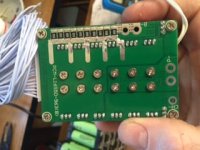
Here's what I've got. Sorry for the upside down photos I'm not sure why they get inverted when I upload..
IMG_0371.JPG
IMG_0369.JPG
IMG_0372.JPG


BMS came from LunaCycle (Taiwanese made). It is 14s 50a continuous 80a burst. I've emailed them and they say there is no schematic available for the unit and haven't yet responded to my request for connection guidance, which has lead me here for help.

I am partly guessing, but this is what I am thinking the connections need to be:

PCM SURFACE
B- = Battery main negative terminal
P- = Controller negative lead
CH- = Charger negative lead

Please advise if this sounds correct. I am a little confused about why there are 2 holes for both the B- and P- terminals... Which one(s) do I use?

HARNESS LEADS
B- = Battery main negative terminal (in addition to the B- lead from PCM SURFACE?) <--- This has me a little confused.
B1 = Battery Series 1 positive terminal
B2 = Battery Series 2 positive terminal
etc..
etc..
B14 = Battery main positive terminal

Thanks in advance for any assistance you could offer. :)
 
sounds correct to me. pictures are a bit small, but i guess i read it correctly.
it's a straight forward thing. battery/power/charger connections are easy, as, as you did, can be assumed by starting letter.
the B- thing is handled differently by different bms makers. it's a good idea to have separate balance wires for ALL cells. and yes B- is the same as the main battery GND, and B14 is the same as battery positive.
you may proceed :)
 
Thanks so much izeman!! I just really didn't want this thing to fizzle. :) It also appears that my BMS has a temp sensor marked with 65c. Does this mean that it would cutoff at 65 degrees Celsius?
 
You're welcome. I have that temp sensor on mine (other type though) as well, and it is connected to the FET's heat sink. Can't say anything about the cut off temp though. You may want to test with a temp controlled heat gun?! Just remember: you have to remove battery power connection completely to reset the bms after it did the safety cut off.
 
Here's the schematic from my BMS.
 
Thanks for sharing tomjasz. That further confirms my thoughts on connection. Can't wait to get it wired up tonight and see how this first battery performs!

That's a great idea izeman. I do have a temp control soldering iron I can probably try to use. Seems a little low for cutoff temp but we will see. Great info I love this forum!!
 
fechter said:
What kind of controller are you using?

Some of them have a programmable setting for Vmax which will inhibit regen when the pack voltage gets up to the limit. This is a first level defense for your battery and should prevent overcharging. It sounds like your controller already does this, so the BMS doesn't really need to.

The real danger is if the pack voltage goes too high during regen, you could fry the cells or fry the controller. I wouldn't worry too much about the regen current since you generally don't use it long enough for heating to be a problem.


I'm using a generic brand from china among others and they all seem similar in construction. Others have mentioned that unless I rode it downhill for 10 minutes straight (rarely have hills that long even at slow speed) it wouldn't have the over-regen charging issue although it seems several commercial scooters have decided not to allow for regen for this reason such as the eco-reco scooter with only a mechanical brake although the etwow scooter has no mechanical brake (save for the rear "friction" brake that rubs on the rear wheel and isn't much of a brake) but does have regen although I haven't heard of any issues with it being "overcharged" through regen at the start of a ride say, down a hill after full charge...

Thx
 
Back
Top