
The switch I used is the stock key switch on the A2B Metro. The bike was already set up for two packs.
You are using an out of date browser. It may not display this or other websites correctly.
You should upgrade or use an alternative browser.
You should upgrade or use an alternative browser.
Bestechpower BMS
- Thread starter dnmun
- Start date
SafeSkyWorks
1 µW
- Joined
- Mar 16, 2016
- Messages
- 1
Hello,
I'm new to this forum and fairly new to the advanced battery LiPo stuff")
My name is Ron and i hope you would be willing to help me since i'm bit confused by all the information im reading.
I will try to explain my situation as good as possible.
Im using Lipo battery's for quit some will now but with tools ready to go, what i mean by that is that i have a imax charger and 6S 16000 Mah battery's for my UAV application.
Now im building my own UAV that needs more power and another battery setup.
Here goes
I have the following test batteries
Battery Spec
LiPo 5S 10000MaH 30C
I have 3x 5S battery in serie (So 15s Total)
4,2V x 15S (Cells) = 63V
63V x 10 = 630Watt
The (safe) charging rate is 1 C
1C = 10Amp
Discharge amp = 300A
What i need for this is a system so i can safely charge this pack in serie so at 15S
I hope you can help me in making the right choice to do this regarding to:
Charger
BMS/PCB (what is the difference ?)
Hope you understand what i mean so far, and can help me making the right choice and offcource can learn for the future of use with this application.
Thank you
Ron
I'm new to this forum and fairly new to the advanced battery LiPo stuff
My name is Ron and i hope you would be willing to help me since i'm bit confused by all the information im reading.
I will try to explain my situation as good as possible.
Im using Lipo battery's for quit some will now but with tools ready to go, what i mean by that is that i have a imax charger and 6S 16000 Mah battery's for my UAV application.
Now im building my own UAV that needs more power and another battery setup.
Here goes
I have the following test batteries
Battery Spec
LiPo 5S 10000MaH 30C
I have 3x 5S battery in serie (So 15s Total)
4,2V x 15S (Cells) = 63V
63V x 10 = 630Watt
The (safe) charging rate is 1 C
1C = 10Amp
Discharge amp = 300A
What i need for this is a system so i can safely charge this pack in serie so at 15S
I hope you can help me in making the right choice to do this regarding to:
Charger
BMS/PCB (what is the difference ?)
Hope you understand what i mean so far, and can help me making the right choice and offcource can learn for the future of use with this application.
Thank you
Ron
Ykick
1 GW
Ron - the nomenclature is: BMS/PCM not PCB. I believe PCM stands for “protection circuit module” but that’s a pure guess.
What current capability does your system need? 300A, 10A? I can’t tell from what you’ve provided?
Now notice you mention UAV so I suppose you only intend to use the BMS/PCM for charging? Wouldn’t want protection to cut power mid-air, would you? If just charging, you can get along with smaller working current BMS/PCM.
Are you really set on 15S? Having used both cell counts extensively in the past I’ve come to realize 16S is often more convenient. More readily achieved by 2qty 8S or 4qty 4S RC Lipo. Not stuck sourcing 5S packs. An extra cell Wh too.
Bestechpower BMS with higher cell counts can readily use lower cell counts. Even if you’re already set on 15S, for future potential upgrade to higher voltage (cell counts) you might wanna start with 16S-20S and just leave the upper cell channels open/disconnected until needed at a later time?
I took it as 300A discharge and 10A charge.
A BMS that can handle 300A is going to be quite large and heavy. If the load (motor) runs directly off the batteries and doesn't go through the BMS, then a much lower rated unit would work. 10A charging is within the capacity of many units, though you may need to upgrade the charge FET.
Normally the BMS will cut all power when a cell gets too low. As Ykick points out, this might be bad for an aircraft. You could possibly pick off the low battery signal from the BMS and use it to trigger something else, like a warning signal. If the cells are healthy and you have some other kind of voltage monitor that looks at the pack voltage, you can probably tell when you run out of juice.
There are a large number of variations in the BMS boards available. There may be several that would work for your application.
Another possible option would be to not use a BMS, but have a way to use multiple balance chargers for charging. This is possible if each balance charger is electrically isolated, meaning each one needs it's own power supply.
tomjasz
1 GW
Bestech seems to be peddling the programmable BMS. Last I heard the MIA OP was waiting for them. Anyone?
izeman
1 GW
I'm waiting for it now for month. I was informed several times that they will arrange shipping, but it seems there are some major delays.
Organichona
1 µW
- Joined
- Mar 23, 2016
- Messages
- 3
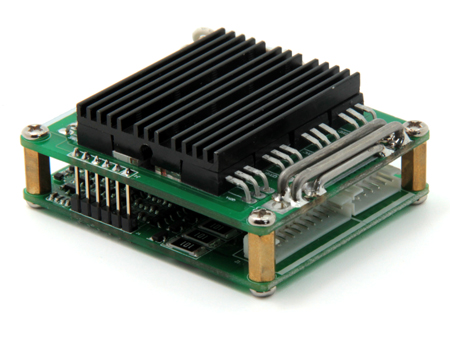
I need information concerning powering up a Bestech HCX-D205, 48V, 20A BMS card with e-switch. I have seen a lot of information about BMS function and purpose but little about installation.
What is the proper sequence to startup?
1. BMS is in series with the negative?
2. Connect negative battery lead?
3. Connect positive lead?
4. Activate - e-switch?
5. Insert JST balance connector at angle, #1 cell first with or without e-switch on?
Have burnt up the 101 resistors on two boards.
What is the proper sequence to startup?
1. BMS is in series with the negative?
2. Connect negative battery lead?
3. Connect positive lead?
4. Activate - e-switch?
5. Insert JST balance connector at angle, #1 cell first with or without e-switch on?
Have burnt up the 101 resistors on two boards.
If the resistors are burning up, double check the wiring between the cells and the balance connector. That can happen when a pair of wires got swapped. Measure voltage from pin 1 to pin 2, then 2 to 3 and so on up the line. You should see a single cell voltage on each pair, something around 4v. I use skinny wire probes that fit into the slots on the wire side of the connector, but any probes that fit will work. Just be very careful not to short the probes when measuring. Do this before attempting to attach the BMS.
If they all look correct, I would attach the battery negative, balance connector, then battery positive, but the order shouldn't really matter if everything else is good. Make sure the charger and controller lines are disconnected until after the other connections are made.
If they all look correct, I would attach the battery negative, balance connector, then battery positive, but the order shouldn't really matter if everything else is good. Make sure the charger and controller lines are disconnected until after the other connections are made.
Ykick
1 GW
The D205 is very similar to the D245 which I have some experience with. It was an odd bugger. However, burning up balance bleed resistors - something's wired wrong.
But when they’re wired properly I know from experience the D245 wouldn’t function until a charge is applied. Once a charge has been applied, just for a brief moment, the BMS/PCM functions fine. No mention of this in documentation and it can be a bad problem if you're out on the road and for some reason disconnect the BMS. It ain't coming back ON without a jolt from a charger or something with higher potential.
http://www.bestechpower.com/481v13spcmbmspcbforli-ionli-polymerbatterypack/
Organichona
1 µW
- Joined
- Mar 23, 2016
- Messages
- 3
I just triple checked the cell balance lead for voltage. I left the positive probe on bottom cell and measured up in approx. 4 volt increments up to 44 v. (The first cell to ground makes up the total 48 volts)
1. Connected Battery Negative to B- on BMS
2. Connected P- to circuit (no load)
3. Install cell balance plug at angle toward cell 1 and insert.
SMOKED ANOTHER TWO 101 RESISTORS ON THE EDGE OF THE NEWBOARD!
1. Connected Battery Negative to B- on BMS
2. Connected P- to circuit (no load)
3. Install cell balance plug at angle toward cell 1 and insert.
SMOKED ANOTHER TWO 101 RESISTORS ON THE EDGE OF THE NEWBOARD!
Which resistors are smoking?
Ykick
1 GW
fechter said:Which resistors are smoking?
This. And why are you plugging the JST connector at an angle? I always avoid doing that.
Ykick said:This. And why are you plugging the JST connector at an angle? I always avoid doing that.
The idea is to make the cell connections sequentially so that you don't get more than one cell voltage across the shunt circuits.
If you attached the pack negative, then say the most positive cell, you'd wind up with a bunch of floating shunt circuits trying to equalize the full pack voltage. This may result in some shunts turning on and giving more than normal voltage to an adjacent cell circuit.
If you just make the connection quick, there shouldn't be enough time to fry anything, but it doesn't hurt to avoid potentially damaging conditions.
GmagNeato
100 W
Received email from Bestech today:
"We have new BMS with CANBUS SMBUS,I2C communication,if you have any new project with these BMS,maybe we can work together?"
For those that don't know yet just thought you might be interested.
G
"We have new BMS with CANBUS SMBUS,I2C communication,if you have any new project with these BMS,maybe we can work together?"
For those that don't know yet just thought you might be interested.
G
Ykick
1 GW
fechter said:Ykick said:This. And why are you plugging the JST connector at an angle? I always avoid doing that.
The idea is to make the cell connections sequentially so that you don't get more than one cell voltage across the shunt circuits.
If you attached the pack negative, then say the most positive cell, you'd wind up with a bunch of floating shunt circuits trying to equalize the full pack voltage. This may result in some shunts turning on and giving more than normal voltage to an adjacent cell circuit.
If you just make the connection quick, there shouldn't be enough time to fry anything, but it doesn't hurt to avoid potentially damaging conditions.
Huh? ‘Seems to me there could be much different interpretations of “sequential” using technique like that?
I always just steady my hands and plug it as straight-in as possible. No dicking around, swift and clean…
There’s 101 resistors not related to balance channels on some of these BMS/PCM. I suppose this guy may be referring to some of those? A picture might help us better help him….
Yeah, the CANBUS spam is out. I don’t deal with these guys anymore. Good circuits, I guess. But too many hoops and BS to bother with for my purposes.
Organichona
1 µW
- Joined
- Mar 23, 2016
- Messages
- 3
Thanks for all of the good information!
It was advised on this site to insert at an angle. I will try again with straight quick action.
I burned up at least two 101 resistors, both sides of lower board level near cell one of the balance plug
It was advised on this site to insert at an angle. I will try again with straight quick action.
I burned up at least two 101 resistors, both sides of lower board level near cell one of the balance plug
Yes, post a picture of which resistors are burning. This will help a lot to figure out what might be happening.
ValeryT
1 µW
- Joined
- Apr 9, 2018
- Messages
- 3
Hi, All
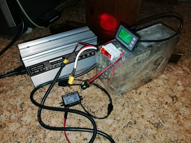
Guys, i have such PCB on my battery HCX-D132
Please help me with PCB disconnecting/connecting. I like to add power metter to battery between battery "-" and PCB.
What is right disconnect and connect order? I mean B- and balancing connectors. Can i just disconnect B- from PCB and reconnect it back if balancing connectors are connected?
Thanks!
As long as all the balance wires stay connected, I think you can disconnect the B- wire to insert your meter without risking blowing the thing up (assuming you don't accidently contact the wrong thing). Just make sure the B- line is intact before turning on the load.
izeman
1 GW
i don't see a need for special connect/disconnect order.
if you only disconnect B- at any time, there is still a connection to most negative cell of the pack by the first balance wire.
if you disconnect the balance wires at all and have the main power leads connected the BMS doesn't care about it.
if you only disconnect B- at any time, there is still a connection to most negative cell of the pack by the first balance wire.
if you disconnect the balance wires at all and have the main power leads connected the BMS doesn't care about it.
izeman said:i don't see a need for special connect/disconnect order.
if you only disconnect B- at any time, there is still a connection to most negative cell of the pack by the first balance wire.
if you disconnect the balance wires at all and have the main power leads connected the BMS doesn't care about it.
For example, if you just connected the B+ and B- wires before anything else, you would have full pack voltage across a bunch of series connected cell circuits. If the cell circuits all shared evenly, this wouldn't be a problem, but what can happen is they don't share evenly and one or more balancing shunts turns on. The voltage across those circuits drops to near zero, which places additional voltage on the remaining cell circuits, triggering more shunts and you get a domino effect. This all happens in milliseconds. The cell circuits blow up at around 12v. I have seen this happen to quite a few boards.
When disconnecting, there is less tendency for the shunts to trigger but you should still avoid having a condition where only the B+ and B- are connected.
Some of the newer board designs may be more tolerant of this (or not). I'm talking about the typical low cost chinese types.
Similar threads
- Replies
- 3
- Views
- 2,472
- Replies
- 7
- Views
- 1,210
- Replies
- 58
- Views
- 33,167