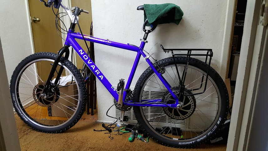
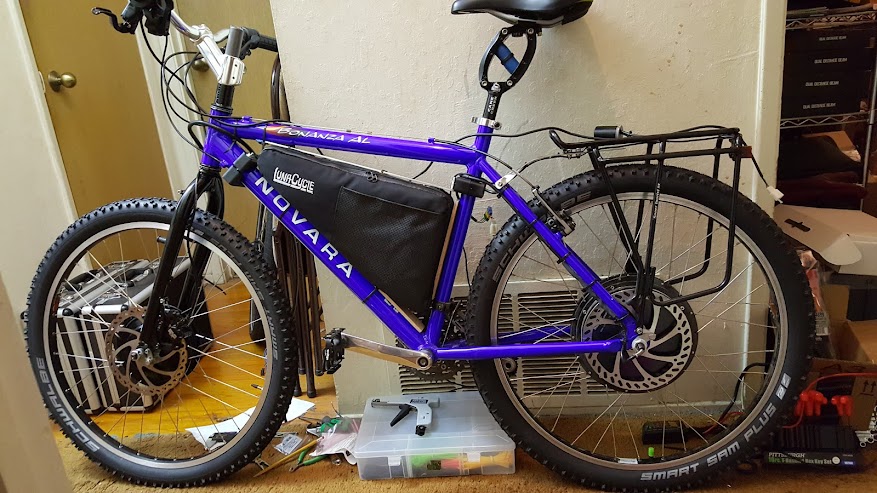
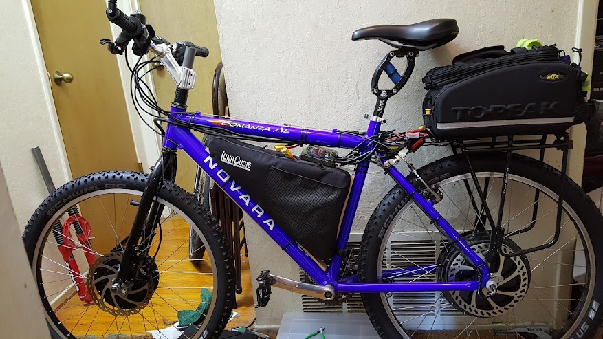
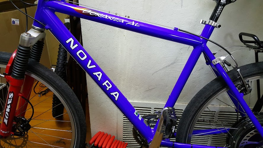
Bonanza AWD Modelling
First of all, I want to start off with thanks to Justin for supplying the motor simulator and providing an excellent and important tool. I'm going to dig a bit and show some things in the Sim that are limitations and some are probably bugs, but understand that all software has limitations and bugs and that especially in sims we must be aware of them and work around them. So this is not a criticism of the simulator.
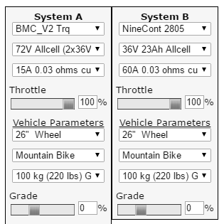
To keep it simple I'm not changing bike system weight, etc as the defaults are not too far off, and as long as they are the same that's fine. The less changed the easier to setup the sim. If you want to repeat this setup it is easy to do, just use the custom controller current values to get the currents, I even left the resistance at the default 0.03 for simplicity. I also selected the largest AllCell 72V and 36V packs. On to details.
Selecting the Motors, batteries, etc. The first problem I have is that neither of the motors I'm running are in the sim, and there's no way to add our own motor to the sim. So we have to find something close. In the BMC list there is a V2T, and I'm guessing it is very close to the V4TT that I have. The improvements to clutches, gears and heavier phase wiring won't make a huge difference to the motor performance. The 9C is a bigger problem. Even though the 9C 2810 motor I have is engraved with ebikes.ca (and apparently came from them, I bought it from ES:methods), it is not in the simulator. The best I can do is to use a 2805 and feed it half the voltage and double the current. One thing we need to keep in mind with this 2805 trick is that the motor current will be double that of the 2810, so anytime we look at B motor current we need to think "actually half of that value".
Choosing Battery Current - the Luna 72V pack BMS is rated for 50A continuous and 70A burst. I'm arbitrarily going to derate the continuous value by 10% and use 45 amps to provide a small margin. I've done quite a bit of modelling already so I'm going to choose 1/3 of that current to go to the front BMC gearmotor and 2/3 to go to the rear 9C DD. Remembering that the 9C we are using in the model runs at half voltage and double current, this results in 36V 60A to system B, while the System A value is 15A at 72V for a 45A total at 72V (half the 60 plus the 15 amps).
I was recommended by the BMC motor vendor (ilia of EbikesSF.com) to keep continuous power at or under 1300W. 72V fully charged is 84V times 15A is 1260W. So 15A is a safe value even at hot off the charger voltage. As we understand the 9C can handle a lot more power, and as we will see it needs more to keep up with (and exceed) the BMC.
The goal here with this 2WD setup is to have about the same thrust from each motor, preferrably a little more from the rear than the front.
In early riding of the 2WD Bonanza the front BMC was really providing a lot of thrust, apparently more than the rear. The initial values of battery current for the BMC were higher at 20A, and this made the BMC dominate the total thrust and made the front wheel want to spin. On pavement this resulted in noise from the tire but no slippage, in dirt the results could be bad, spinning out this wheel. We want it to pull, not spin. On to the settings:
And then the good stuff:
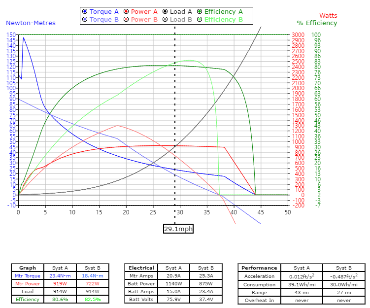
Now let's go through this and attempt to understand what it is telling us in detail. The graph above shows both motors in "full throttle" over the entire range of speed from 0 to 50 mph. My apologies to the metric folks. Torque is in Nm so we are mixing modes and annoying everyone a bit. At any rate, values to the left of the equilibrium point, which is 29.1 mph for the BMC, and a little less for the 9C are in the acceleration region, and values to the right are not going to happen, except after a big hill as we decelerate back to equilibrium on the level. Equilibrium occurs when the load line crosses the motor power line, so when the power and the losses are the same. From experience I can say that this is a 28 mph machine at 72V, so these values are in the right neighborhood.
This graph looks fairly well matched, if we look at torque from both motors (the blue lines), the BMC starts out higher, at 6 mph the 9C takes over, and at 27 the BMC again takes over as the back EMF from the 9C reduces its power. We want the 9C to have greater torque all across the curve, so we'll be making adjustments to accomplish that. Now what about that crazy stuff at very low speed?
Now we need to understand that the simulator is a complicated piece of software and it doesn't take everything into account, and there are always some bugs in software. We need to always be on the lookout for simulator anomalies, and we have some here.
If we look at 0.5 mph (if you run the sim and click on it you can get to these values in the boxes) we see the BMC battery current is 15 amps, as we requested. However at 1.1 mph the battery current is 27.8 amps, almost double what we requested the limit be. This makes the crazy 145 Nm torque value shown. We don't want this torque level on the BMC, it might break clutches and gear teeth, and the PhaseRunner controllers are very good at controlling actual motor current (which trap controllers generally are poor at doing). In fact, at these very low speeds we don't even want the full 15 amps of battery current since the current multiplication of the controller could produce more motor current and torque than we want. So we set a motor phase current limit in the PhaseRunner. But what value?
We know the 9C has a knee in the torque curve at about 468 ampere turns, right at 70 Nm, where the efficiency starts to fall off somewhat. Justin measured this in a thread:
https://endless-sphere.com/forums/viewtopic.php?f=2&t=14494&start=25
If we look at 70 Nm that shows about 90A for the 2805 motor in the sim, so it will be about 45-47A for the 2810 that I have. You can drive more current than this, but the efficiency is reduced, and Justin was finding that even at this level the motor and phase wiring was heating up a lot. So this is a good value for the max torque, or slightly higher if you want more torque and don't mind losing a tiny bit of efficiency and heating the motor a bit (as long as it is only for short periods). Perhaps we should choose 50 amps just for a round number as the 9C 2810 max motor current. Pushing on the pedals will increase the rear wheel torque a lot at these low speeds as well. I've found it is easy to pedal the rear wheel to spin in steep dirt situations.
Since the Kv of these motors is nearly matched (The PhaseRunner measured 5.5 for the BMC and 5.3 for the 9C) that means the Kt torque constants are also nearly matched (since they are reciprocally related constants). This means the BMC produces slightly more speed per volt and slightly less torque per amp, the difference to this 9C being about 5%. So we want the motor current limit for the BMC to be a bit lower than the 9C to keep the BMC torque lower. If we make the current the same the BMC torque will be about 5% lower, and we want it even a bit lower yet, so let's make the BMC max motor phase current be 45A, so the BMC torque will be about 15% reduced compared to the 9C.
So what will that do to this graph? The lower part of the torque curves will flatten out from zero speed to where they start dropping naturally, with the 9C at about 70 Nm and the BMC at about 60 Nm. Pretty good hill climbing power without overstressing the BMC gear and clutches and without heating the 9C too fast. With 2WD each motor only has about half the load to deal with.
Now at the high end of the speed range, around 27 mph, the BMC and 9C torque curves cross again. We don't want the BMC torque to rise above the 9C torque at high speed. ilia was concerned about this and suggested that the BMC be shut off at high speeds. We could easily do that, but we have another choice with the PhaseRunner controllers - to use Field Weakening to reduce the back EMF of the 9C a bit and push it harder at the high speed end. Not to go faster, but to balance the torque. The simulator won't handle field weakening, so we'll have to experiment. Perhaps we will shut the BMC off at 28.
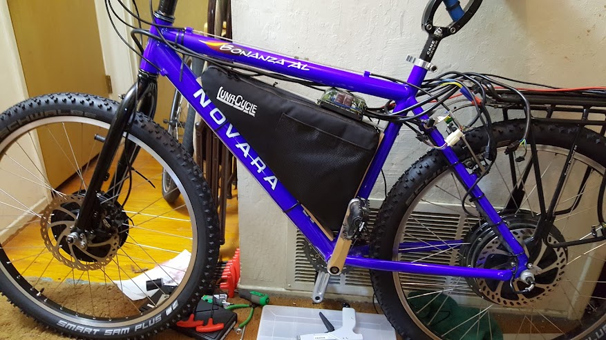
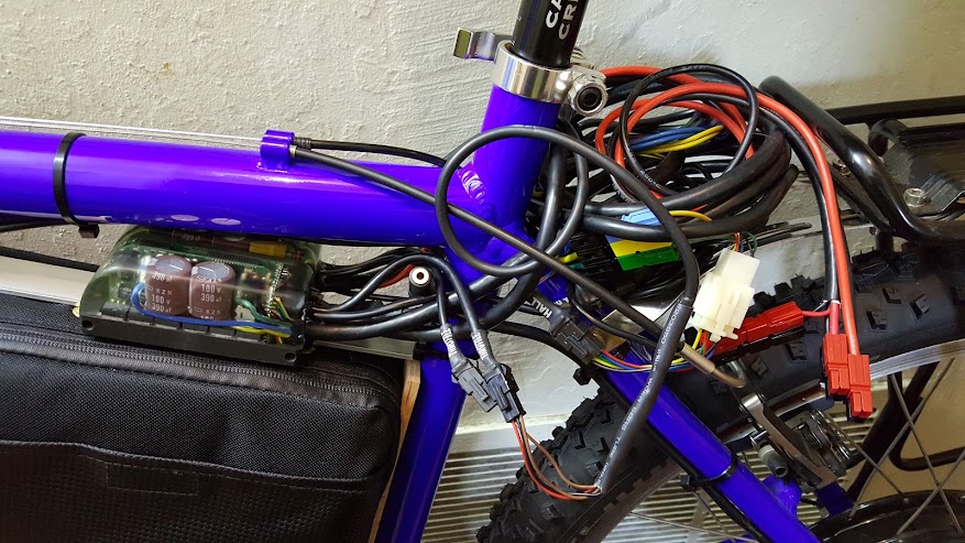
I'm going to install a pair of Cycle Analysts so I can look at both motors as these adjustments are fine tuned. I can use a chest mounted GoPro to record the data so I don't have to look away from the road too long, and can ride on various gradients and see how the power balances. It doesn't have to be a perfect balance but we don't want any surprises or PhaseRunner trips.
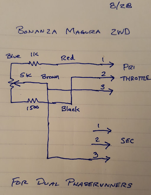
Some have asked me about the motor speeds being matched and what happens when they are not with a 2WD ebike. With a pair of trap controllers being fed the same throttle signal you do want matched tire speeds, so the Kv should be equal (equal speed, so tire size could be used to make up for differences in Kv). Here we have two PhaseRunner Field Oriented Controllers that take the throttle signal as a torque request. This compensates for speed automatically so the motor Kvs don't need to match at all. If you dial to 50% throttle each controller will work to produce 50% torque, automatically compensating for the speed of the wheel. It is a nearly ideal setup and is one of the reasons I decided to use dual PhaseRunners on this project. They are also a lot smaller and easier to place on the bike, and they have fewer wires than the usual trap controllers.

")