Building my E-Bike

as i am browsing thru your weblog recumpence, i came to think of the chain idlers and wanted to share :)

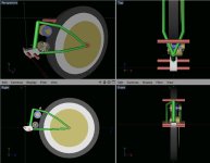
i will use skateboard or rollerblade wheels with groove for chain cut into them.
eather cut the groove in a lathe or simply by fastening them on the spindle of my handheld electric drill.

axles already ready, with 2 ball bearings each :)

there will be some wear on the wheel rubber initially, but as it finds its shape it will last long enough :)


by the way, i must mention, im copying you pretty much right off here recumpence.. :)

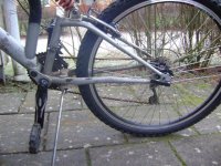
i will do the gearbox/motor assembly slightly different since im fitting it onto my dampened mountainbike (pictures to come soon) but you owe most of the credit for this project :)
 
Ive done some sketching in my 3d app. The measurements are supposed to be fairly accurate, even tho the angles are probably off.

But it shows my basic plan..

i also calculated the size for the gear assembly and found that if my sketch is correct i will have to use aprox 10:1 ratio on the last stage (to wheel), hence the huge sprocket (sprockets are brownish on the sketch)


The red rods are position markers for important axles, wheel, connection points for suspension and pedal axle.

Motor at the bottom (to keep as close to pivoting centrum as possible) geared hub just below the suspension structure.

ESC will be placed under saddle and gauges, throttle and so on will be snap-on for easy removal.
Batteries in pockets/backpack.


I really need smaller diameter sprockets for stage one, was thinking motorbike drivetrain, but the sizes are wrong.. :(

there will be some serous rpm on this stage, aswel as some moderate stress aswell.

prehaps it would be best to use a v-belt or similar at this first stage, to be used as a friction clutch in case shit hits the fan.


i belive i have some good ideas about the drivetrain, but im totally lost in the power transmission part..
So any input is greatly appreciated :)


I will measure everything and sketch it more accurately when the motor arrives next week and start test the motor to figure out the exact gear ratio :)
 

Attachments

  • motor assembly sketch.jpeg
    motor assembly sketch.jpeg
    50.3 KB · Views: 1,391
Here´s a picture of the bike im converting :)
probably makes it easier to understand what im planning :)
 

Attachments

  • rear wheel.jpg
    rear wheel.jpg
    73 KB · Views: 2,070
cargo said:
Which hub gear do you intend to use?. Will there be enough room for it width-wise.?

I havent gotten that far in the progress yet. The gear is so far very optional, and will eventually have to be removed anyways (since it probably wont cope almost 3kW of power :) ).

The motor is now at customs waiting to be declared, and i really cant wait untill i get my hands on that monster :D

its time to start doing the blueprints with every bolt, bell and wistle in detail, so i can start fabricating the parts.

Im starting to worry that im over-estimating the gearing ratio needed, so i humbly ask what the forum gurus have to say..?
care to estimate a proper ratio?
 
Hi,

xarvox said:
cargo said:
Which hub gear do you intend to use?. Will there be enough room for it width-wise.?

I havent gotten that far in the progress yet. The gear is so far very optional, and will eventually have to be removed anyways (since it probably wont cope almost 3kW of power :) ).

Im starting to worry that im over-estimating the gearing ratio needed, so i humbly ask what the forum gurus have to say..?
care to estimate a proper ratio?

There are a lot of posts on this topic by Gary, Miles, Matt and D. I think in either the "High Power Drive" or 'Freewheel Crank Resources" threads.

The general approach I would use is to decide what top speed you require, gear accordingly and if the low end isn't good enough increase your amps and/or voltage (increasing reduction).

Read the complete thread on Scott's build (same motor). Based on his issues, using a 24v system without the Nexus I think I would start with about 18:1, which I think would give you about a 40kph top speed. You might find you need either more reduction or more amps for good enough low end.

The Nexus will be a huge help and I think if you don't abuse it it will be OK. Gary hasn't had any problems with 2.6kw peaks (I don't think your motor will sustain even close to 3kw). With the Nexus you could use more reduction, get a higher top speed and better low end acceleration.

This calculator should help (I would plug in 80 or 85% of kv [160] for the kv):
http://www.endless-sphere.com/forums/viewtopic.php?f=28&p=120912
Geardown-speed calculator - created by johnrobholmes (see attachment)
 
Ok, the plan has changed a slight bit.. :)

as with many of my projects, i start on one thing and end up with something completely different :)


The current plan is a single stage transmission with 1:9,2 ratio (10T and 92T gocart sprockets) with chain and chain-tensioner.
With my latest calculations (estimating load) it means aprox 25km/h on 5s and aprox 40 with 8s.

This turned out to be the by far cheapest alternative, aprox 50€ or so including shipping.

Now i just have to draw and fabricate the motor housing and rear sprocket adapter (basicly a donut-shaped plate bolted on both sides of the 20mm gap)


this has been very cheap so far, aprox 250€ so far for complete electronics, aditional 20 or so for bits and bobs, so about 320€ in total including gears.


ive also started looking at throttle controls and i think i will go with a pistol throttle on left side (removing the front deraillour).
I will be using servo tester to control the esc, but i got some ideas on howto make the pot controllable by wire :)

The battery will be pretty limited for the time being (only 4,4Ah 5s lipo) but it will do for now.

The long term goal is to build a transportation box on wheels for my rc aircrafts, so i can get out flying more often.
And in that box im planning on putting some lead batteries to juice the bike while saving my lipo´s for flying..
It really doesnt hurt that my rc battery charger has dual input (12v/240v), meaning i could even charge on-site :D


But the last pieces in the puzzle will probably take the longest time (measuring, designing and fabricating) so i doubt i´ll be driving it anytime soon :/
 
Hi,

xarvox said:
ive also started looking at throttle controls and i think i will go with a pistol throttle on left side (removing the front deraillour).
I will be using servo tester to control the esc, but i got some ideas on howto make the pot controllable by wire :)

http://www.endless-sphere.com/forums/viewtopic.php?f=28&t=8160&start=0&st=0&sk=t&sd=a
Fechter's Throttle Interface for RC controllers

http://www.endless-sphere.com/forums/viewtopic.php?f=28&t=8160&st=0&sk=t&sd=a&start=30#p123568

Postby GGoodrum on Fri Jan 09, 2009 1:05 pm

I'm getting some test boards made, which I should get back early next week. Here's what it will look like

The large caps are 330uF/100V. That should be more than enough to help the controller. As Richard pointed out, some of the resistor values might need to be tweaked a bit, here and there, but hopefully by this time next week, we will have that all sorted out.

I will try mine with my Hacker-based test setup, which I'm hoping to get up and running this weekend.
 
I will order the sprockets next week so i will have a complete drivetrain by the end of this month :)

some bits are still missing a final solution, i dont think its a good idea to run a "stiff" drivetrain, without any type of clutch/one way bearing.

the easiest so far would be gocart clutch, but they arent exactly optimal for electric motors as they require a certain rpm to engage.

the rear wheel sprocket area isnt possible to modify as the space is extremely limited.
The sprocket is 230mm outer diameter, meaning i will have to fit a chain tensioner (skateboard wheel with a groove cut into it) to clear the bottom of the frame.

The motor axle is cylindrical without any mounting surfaces, so i will have to fabric a adaptor to fit anything to the motor, and the clutch is pretty tight inner diameter (aprox 14mm)..

A 2-stage reduction would simplify this as a bike hub would then be mounted above the motor, a better location for a straight chain without clearance-problems.

So a 2stage reduction does have some advantages even tho it would cost a bit in efficiency..
But the question is if i could make it small enough, to build a friction clutch to fit on the motor axle.


I will spend the evening thinking about this, and if you guys know of any smart clutch/freewheel solutions, please post a link :)
 
Hi,

some bits are still missing a final solution, i dont think its a good idea to run a "stiff" drivetrain, without any type of clutch/one way bearing.

If your drive isn't going through the Crank/Pedals the advantage of no FW or one way is you could use regen.

I will spend the evening thinking about this, and if you guys know of any smart clutch/freewheel solutions, please post a link

White makes the best FW's (use Google for the best prices):
http://www.whiteind.com/singlespeedgearing/freewheels.html

In use:
http://www.endless-sphere.com/forums/viewtopic.php?f=6&t=1757&st=0&sk=t&sd=a&start=45

One ways:
https://sdp-si.com/eStore/PartDetail.asp?Opener=Group&PartID=20027&GroupID=388

http://www.renold.com/Products/SpragClutchFreewheels/Sprag_Clutch_Index.asp

Same motor:
http://endless-sphere.com/forums/viewtopic.php?f=6&t=5168&st=0&sk=t&sd=a&start=180#p123731
I fried a few more of these motors but have been running the same one for the last 2 months with no issues. I have had to mod the endbelll to accept 4 fan blades. These draw air in at the endbell and pass it out the 'stator' end (where it fixes to the mount). I have not tried it again on 36 or 48V for 2 reasons. Firstly I don't want to burn any more motors and secondly 35mph is more than adequate for around town since the limit is generally 30mph or less. This modded motor does run a lot cooler - without the blades it would rise about 50C on an extended run up-hill. On a warm day that was problematic since once the bell passes 78C the motors are toasted. With the modded bell the rise is more like 40C.

Oh yeah - the 10,000mfd cap I added has sorted the start-up issues - it now pulls without glitch from a standstill but I do prefer to pedal to 3mph or so before peddaling - for obvious reasons:)

EDIT - ADDITION:
The current plan is a single stage transmission with 1:9,2 ratio (10T and 92T gocart sprockets) with chain and chain-tensioner.

Scott (same motor with 24v) used 9:1 and had very poor low end acceleration (up to about 20 or 25mph). I think he had a more powerful battery pack also.
END EDIT - ADDITION:
 
i figure its time for a slight update..

the gears arrived today, a 10T for the motor and a 92T for the rear wheel.

for the moment the acceleration isnt my top priority, but i need to get this project running in order to improve it further :)


Ive started designing the gear adapters and the motor mount assembly but im very insecure regarding the forces involved..

will a few mm thick aluminum sheet be enough?
i was thinking of bending a a sheet and weld another side to it, to make a 3-sided cube.
With the motor mounted inside it i will then get a "top" and "front" walls, aswell as a motor mounting wall.


Ive started a project with some fellow rc plane junkies, to create a throttle device between the speed controller and a electric bike throttle (found locally for about $30) that will limit the max amp drawn from battery and set by a pot, meaning i wont risk burning my precious drivetrain :D

Im not hoping for miracles tho, but hopefully i will get the device operational within a few months.. untill then i will suffice with manual gauges and manual throttle management with my servo tester.


Well, i got a few bits and bobs to work out, but im hoping for a test-ride within a month :D

this is not the end result, just a step in the right direction :D
 
xarvox said:
Ive started a project with some fellow rc plane junkies, to create a throttle device between the speed controller and a electric bike throttle (found locally for about $30) that will limit the max amp drawn from battery and set by a pot, meaning i wont risk burning my precious drivetrain :D

Checkout this: http://www.endless-sphere.com/forums/viewtopic.php?f=28&t=8160
 
Thanks for the link, but ive got some other plans for it :)
I did get some good hints and ideas tho, to add throttle cut button to connect to the breaks among other things :)


I did some machining this weekend, fixed the sprockets onto the motor and rear wheel, but ended up with a pile of problems.

I failed to bring my camera so still no pictures.. :( sorry..

The rear wheel frame wasnt wide enough to allow such large diameter sprocket and will not allow me to easily run a chain thru/around it.

We did some "manual ajustments" with a hammer on the frame and ajusted the rear wheel sprocket mounting, so now the wheel freely rotates and there´s clearance for the chain, but i cant get a straight angle to any possible motor-locations..

As i see it there´s only three possible solutions for this:
1: mount chain guide wheels on both sides of the chain at the rear sprocket to clear the frame
2: build a structure to allow motor mount above rear wheel.
3: scratch the rear wheel drive and steal my brothers old front wheel with disk brake mount.


The downsides are obvious..
1 will drop efficiency and make more noice
2 will move the weight even further from the pivoting point (fully springdampened bike) making it very shock and vibration-prone.
3, all the weight at front, but on the other hand, easier cable management :)


this hump in the road drained my energy a bit, so i wont be doing anything with the bike for a while..
But what would you suggest as solution?
 
Hi,

xarvox said:
We did some "manual adjustments" with a hammer on the frame and adjusted the rear wheel sprocket mounting, so now the wheel freely rotates and there´s clearance for the chain, but i cant get a straight angle to any possible motor-locations..

Please be extremely careful bending the frame. You could weaken the frame.

xarvox said:
The rear wheel frame wasn't wide enough to allow such large diameter sprocket and will not allow me to easily run a chain thru/around it.

As i see it there´s only three possible solutions for this:
1: mount chain guide wheels on both sides of the chain at the rear sprocket to clear the frame
2: build a structure to allow motor mount above rear wheel.
3: scratch the rear wheel drive and steal my brothers old front wheel with disk brake mount.

The downsides are obvious..
1 will drop efficiency and make more noise.
2 will move the weight even further from the pivoting point (fully springdampened bike) making it very shock and vibration-prone.
3, all the weight at front, but on the other hand, easier cable management :)

But what would you suggest as solution?

I think your best options are:
Number two "motor mount above rear wheel" I don't think the weight will be a big deal. The weight won't any further from the pivot point than a hub motor. Decanio used a Puma which I think weighs about 8 pounds. He used the bike for riding on trails. One of the reasons he was interested in an RC Motor was the reduced weight but on the other hand he never complained about the effect on handling. If you could make a fender that is structurally strong enough for a motor mount you could probably move the motor mount location forward and down to some extent.

Use a design that mounts the motor in the triangle and drive through the cranks, like this:
Rahmen%2003.jpg


Or something like this:
file.php

file.php

http://endless-sphere.com/forums/viewtopic.php?f=28&t=7791&st=0&sk=t&sd=a&start=15#p125944
 
Back
Top