nicobie
100 MW
That looks like it was a lot of work. Well done!


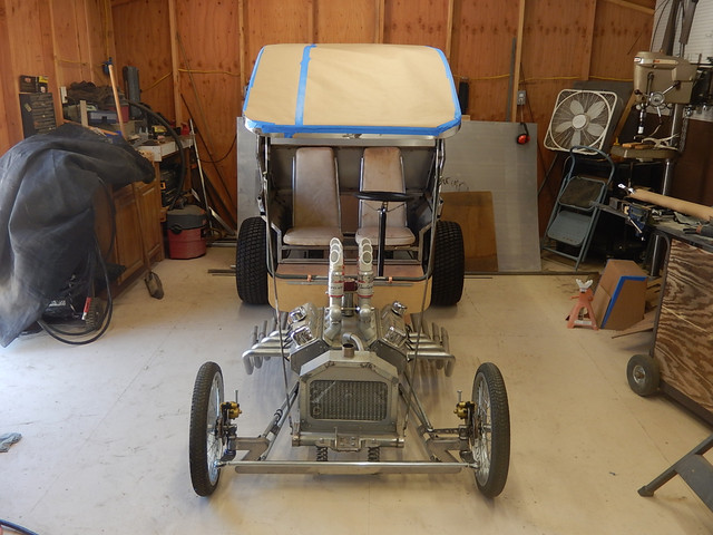


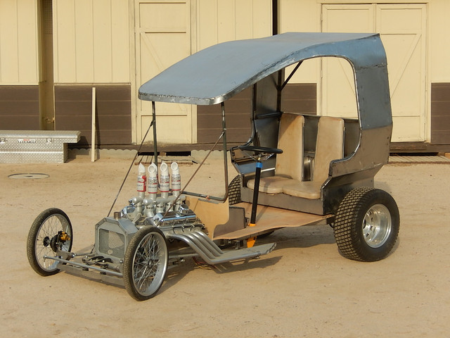
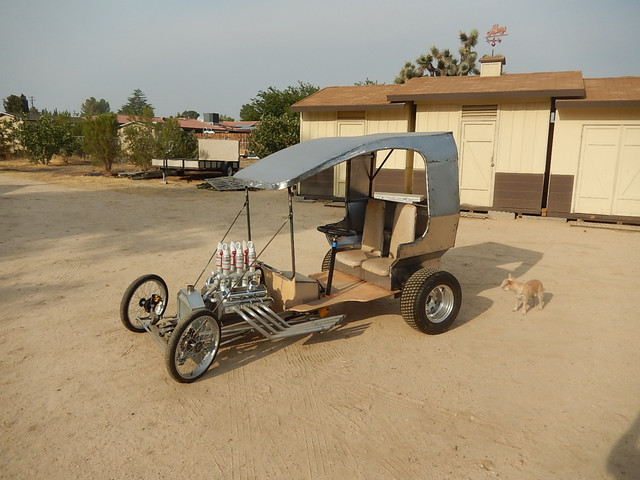
fechter said:Nice. I would prefer a solid top but that might be an issue for the ejection seat.
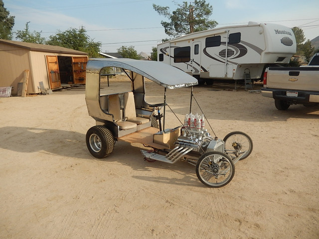
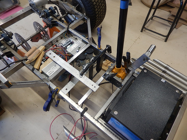
I don’t see any brake hoses yet so I guess too early for a test drive.
You might want to periodically check your battery voltage just to make sure it isn’t slowly draining. It should stay ok for a long time without changing but some BMS units can drain over time.
SlowCo said:Great progress again.
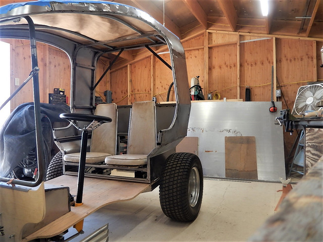
The steering wheel does seem too far away from the seat?
And you should cover the top with flexible solar panels so they can charge the batteries 8)


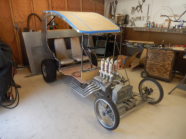
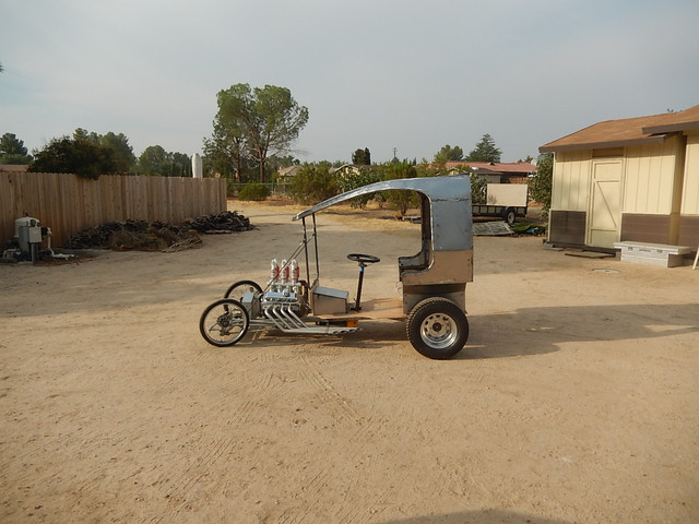
SlowCo said:Steering wheel position does look less far away then it first appeared without you in the Hot Rod. How does it feel though? Wouldn't it be a more relaxed driving position with the steering wheel tilted a little more towards you and maybe a bit higher? I think that when you unbolt the steering wheel and just hold it in your hands when sitting upright in the seat that the "natural" position you would keep the wheel is at least 4 to 5 inches closer to yourself and away from the mounted position as it is now. Not in any way meant as negative feedback only commenting from far away and admiring your work :thumb:

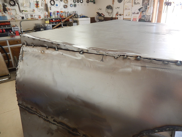


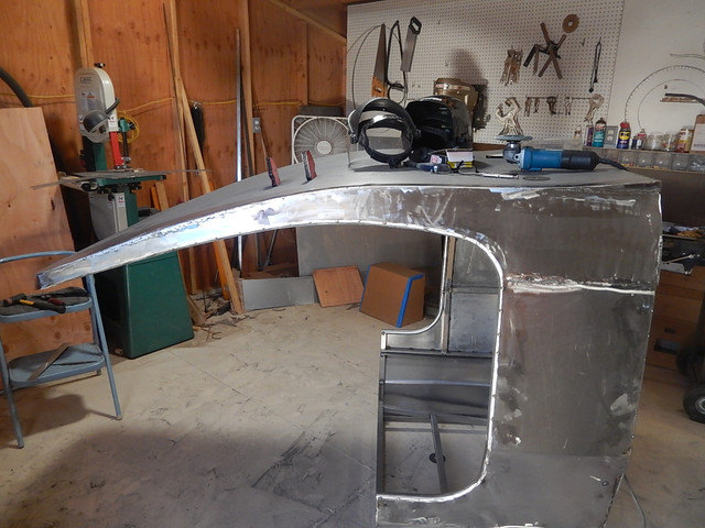
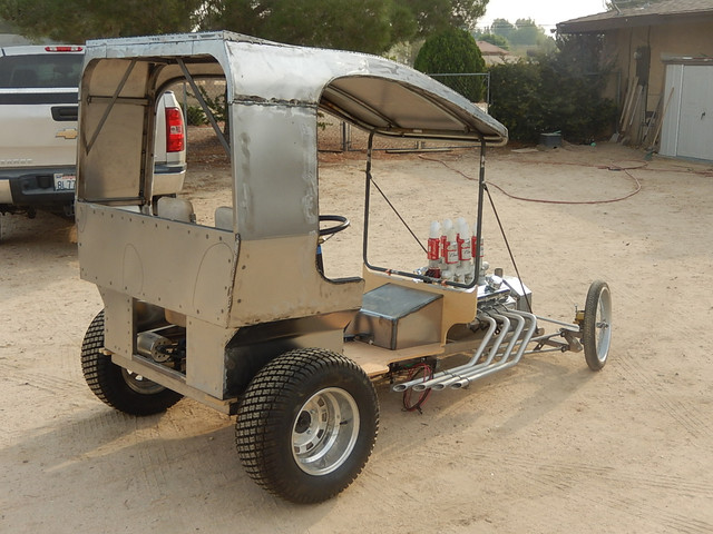
nicobie said:It's coming along nicely! You are getting pretty good with body work.
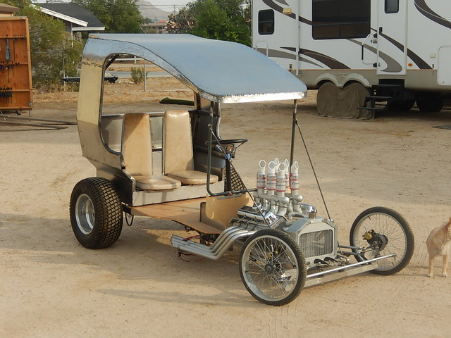
The body lines are pleasing too. It's probably just me, but I'd get rid of the Budweiser cans or maybe paint them. They look a bit tacky to me. Let Budweiser pay for their own advertising. They can afford it.
fechter said:Sweet!
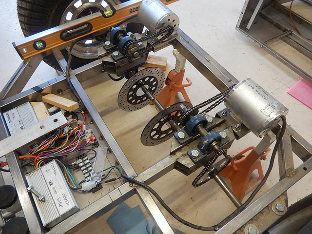
Have you been able to test drive it yet? Looks like the brakes are mounted.
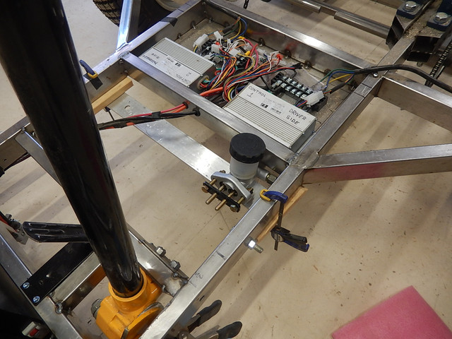
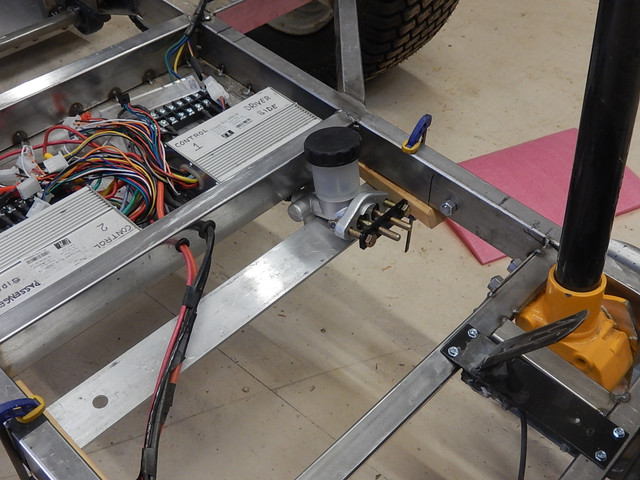
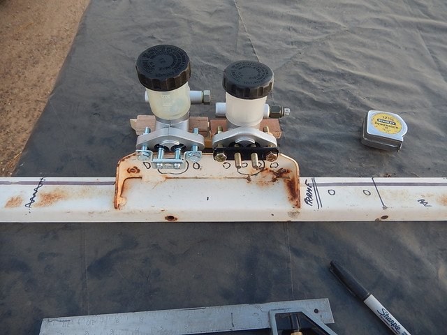
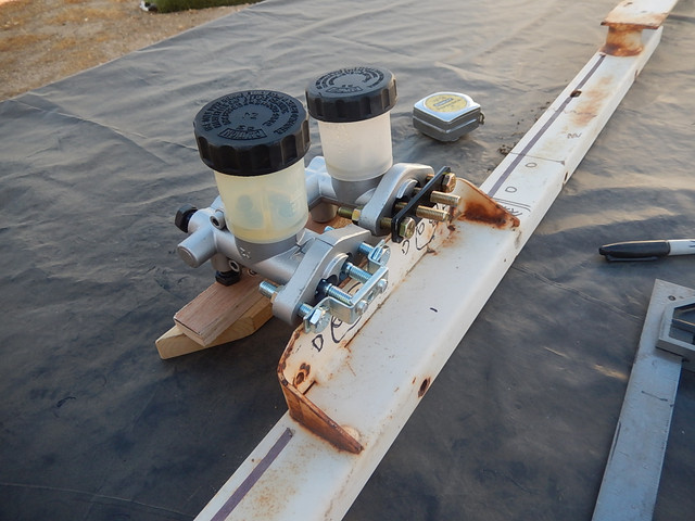
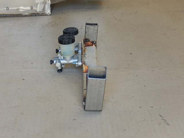
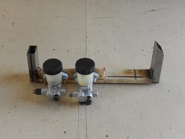


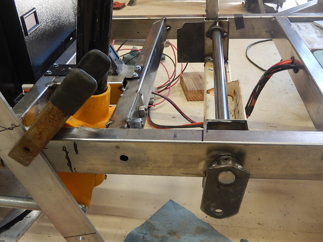
fechter said:There might be a tendency for one cylinder to travel a bit further than the other resulting in uneven force. I guess cars with dual cylinder brakes are like this too and they work, but I was thinking you might want some kind of linkage that applies equal force to both cylinders. If there is some adjustment, that might be good enough.
by fechter » Sep 28 2020 9:18am
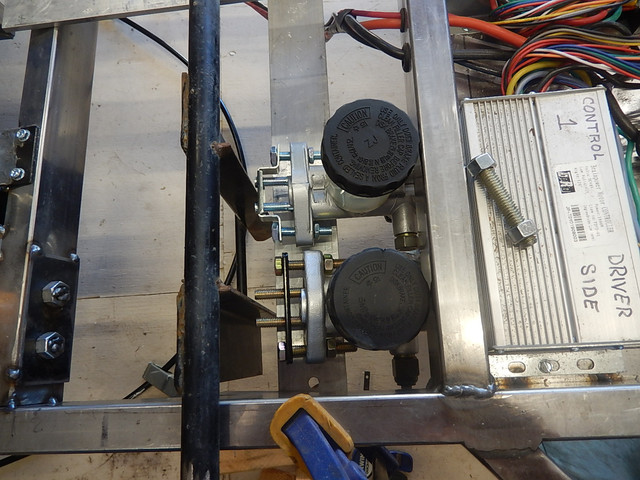
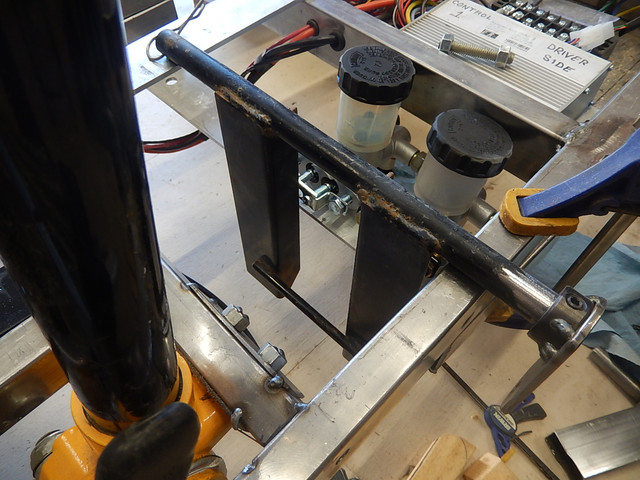
If you had a bar that goes across both actuators and push on the middle of the bar with a pivot, the force would always be equal on both actuators. If the pivot was off center a little, you could have more force on one side than the other if you wanted that. In your case, I think equal will be good.
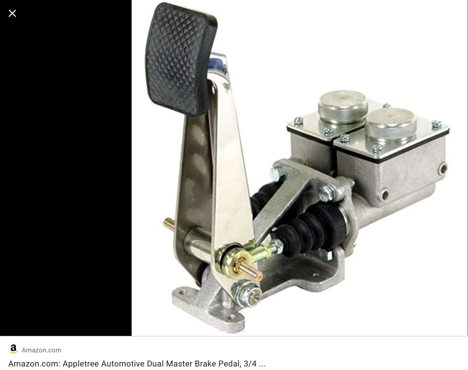
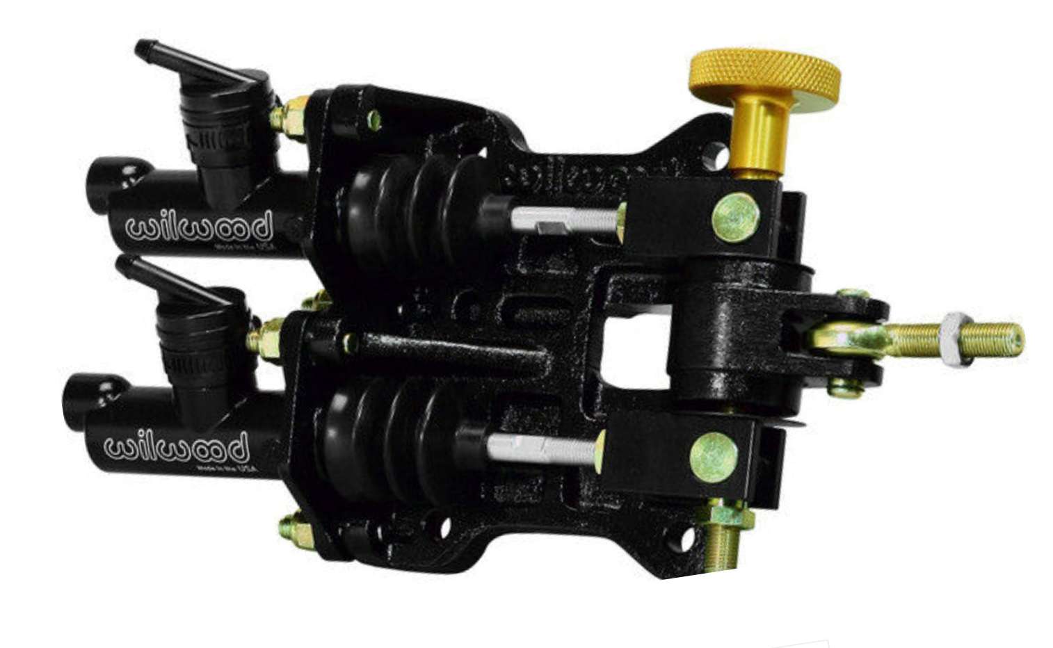
fechter said:If you had a bar that goes across both actuators and push on the middle of the bar with a pivot, the force would always be equal on both actuators. If the pivot was off center a little, you could have more force on one side than the other if you wanted that. In your case, I think equal will be good.