C Cab Hot Rod Power Advice

While I contemplate how and what to do about the brake issue, I started working on something that's been needing to get done for a long while. Both suppliers of the same brake kit are 'Out-of-Stock'. No time when they will be in stock again.

So in the meantime, I needed to get the exhaust pipe support brackets made.
It's taken two days to get the first one completed.
Priority yard maintenance, dryer repair, weed control, just to name a few distractions.

Anyway, the left side is done, and if I don't repeat my mistakes from this one, it will be much easier.

Each 'ring' can swivel and is attached separately.

DSCN4504.JPG
 

Attachments

  • DSCN4505.JPG
    DSCN4505.JPG
    280.2 KB · Views: 1,149
  • DSCN4506.JPG
    DSCN4506.JPG
    282.8 KB · Views: 1,149
  • DSCN4507.JPG
    DSCN4507.JPG
    293.7 KB · Views: 1,149
  • DSCN4509.JPG
    DSCN4509.JPG
    295.9 KB · Views: 1,149
  • DSCN4511.JPG
    DSCN4511.JPG
    263.4 KB · Views: 1,149
  • DSCN4512.JPG
    DSCN4512.JPG
    272.6 KB · Views: 1,149
I ventured out into the deadly virus world yesterday, (mask and all), to get my welding tank refilled.
It is considered 'essential' because there will be no welding without it. And I'm not going back to 'flux-core'.
There were 5 employees there and I was the only one wearing a mask. All millennials. . . so that explains a lot.

In the meantime, I'm still trying to track down a seller of this brake kit.
https://www.ebay.com/itm/142780771945

I have located three sellers that are reasonable in their pricing. Two sellers at $119, and one at $129. (All free shipping)
But they are all out-of-stock. ....Go figure!

I contacted one other supplier https://www.gopowersports.com/150-cc-brake-kit-discs-included/ and they want $179 (plus shipping) (total $193) for the same exact item.
Of course, they are the only one have it in stock. Maybe their pricing is why. They replied, that they don't price match. I would have entertained a reasonable offer on their part, but no, they don't want/need to sell to me.

I'm still wondering about your comment fetcher. The one about the possibility of pulling to one side if I were to use just one brake on the rear. Considering the low speed (25mph max), I wonder how much of a problem it would be.

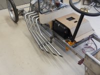
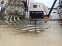
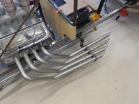
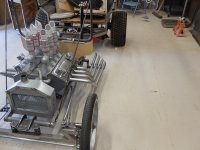
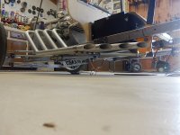
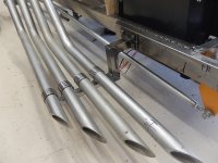
Today I spent time working on the passenger side pipe brackets.

I thought I was out of 5/16" rivnuts. I did find a packet of them properly stored underneath all the debris on top of my workbench.
Anyway, my day didn't start well at all. I drilled out the first hole but couldn't get the rivnut to seat, no matter what I did.
I tried welding it, but even that didn't work.

After ruining two rivnuts and grinding away at the side of my frame I decided it was time to take a break.
Break time, and thoughts of what to do. I had four holes to drill and four inserts to install, and nothing is going right.

Back to my mind-saving YouTube for inspiration and re-education of how to make DIY rivnut tools.
After my refresher course, I ventured back out and tried again.

Welding issue resolved...

Things are better since I turned the... flow gauge back on.
With my gas now flowing as it should I could concentrate on the 'why aren't the rivnuts seating.

Then the 💡 came on, and I discovered why I was having such a time keeping the rivnuts from turning.

I figured it was about time that I make a proper DIY rivnut tool. So here is my version, and so far it is working as it should.


Result with a used sacrificial nut.


3/8 " and 5/16 "


My HF rivnut tool works just fine, up to 1/4", but I want to use 5/16 and 3/8.
So I need to buy a larger more expensive tool or try to make my own for just those two sizes.


My problem was thought to be the hole size. Not so much.
The rivnut would constantly turn because of the design and manner with which I was using my previous tool.
With this design, (thanks YouTube) it works as intended.
I am able to use the 'handle/guide' for both sizes.

With this version, I'm able to hold the bolt and the guide arm at the same time.
Previous versions (also learned on YouTube) didn't work as well as this one.

 
Whatever it takes, to purchase some brakes.

I've found only four suppliers that offer the brake kit I'm interested in.
One is 'in stock' but priced way to high, and won't come down.
One is ' out of stock' but priced 'OK' and requires a (pre-order) for a May 28 shipping date. ETA by June 4.
Two are 'out of stock' and have the best price, but neither has replied to my email info requests.

So I finally bit the bullet and placed my pre-order, for one kit.
https://www.monsterscooterparts.com/brake-kit-with-master-cylinder-calipers-hoses-for-go-karts.html

I will have to work on other matters while I wait for the brakes to arrive.
I'm currently working on the plywood floorboard and the rear panel.
I could work on making a 'console' cover for the battery, as well.
There are headlight brackets that need to be made.
Plus there is some final welding I could get done, while I have the body off.
With the floorboard in (temp), I can see where/how the wiring needs to get from A to B.
 
nicobie said:
Haven't heard from you for awhile. How is the build going?

Being quite honest, I have run into a bit of 'burn-out'. I got the brackets made for holding the exhaust pipes and ran out of steam. I'm also dealing with a slight flare-up of my 'achy breaky' feet. So between home/yard maintenance and standing around working on the car, they are yelling at me frequently.

I've had my brakes on order for a few days now, which will entail a bit of work, designing and making brackets for them.

In the meantime, I changed directions and went back working on the body. I noticed a long while back that the rear corners did not match. So I finally took the time to redo them. Can't explain how the left corner (pictured) became so far out of whack. I think the top bow was welded in at a very slight angle, which didn't become apparent until the side panels were tacked into place. At least that's going to be my story.

I had to grind off all the tack welds and pry open (reposition) the panel. The gap looks a whole lot worse than it really was. All is back together and none the worse.

I picked up another 4x8x20 gauge sheet, to complete the top. The body weight is steadily climbing, but I'm not going to sacrifice style for fear of weight. If need be I will get more power. My latest style for the top is a solid sheet (39 x 69) with 'ghost' flames.

DSCN4544.JPGDSCN4545.JPGDSCN4547.JPGDSCN4548.JPG

In addition to the top, I have cut out the floorboard, using 1/2" underlay plywood. The latest thought for a covering will be automotive carpet in tan/beige. It should contrast well with the red metallic I'm planning on using.

DSCN4539.JPG
 
I've been noticing that burned-out feeling a lot lately and my projects are far less ambitious. I think it has to do with being locked down from the virus for so long. But I do feel better whenever I complete something.

Once your brakes show up, you'll be on the verge of that first test drive. Looking great so far.
 
fechter said:
I've been noticing that burned-out feeling a lot lately and my projects are far less ambitious. I think it has to do with being locked down from the virus for so long. But I do feel better whenever I complete something.

Once your brakes show up, you'll be on the verge of that first test drive. Looking great so far.

I could go for a few days camping, right about now.
We just got tested and our results are negative. So that means I can't infect anyone... right?
The masks are for the protection of others...right?

Maybe I will just go camping in our backyard. No cheating to use the house bathroom either.
It really would be convenient, as my trailer is parked about 25 feet from my shop.

Hmmmm, getting away without having to drive anywhere.
 
I can't believe how time flies.

How come the time machine was so much slower when I was working, 12 to 18 hours a day.
Now that I'm retired, I've slowed down, but the time, it's on... warp speed ?
At this rate, I'll be in my grave before I get this completed.

Better finish this post while I still have life in me.
But 'priorities'... Took time to make a roll-a-round plant stand for the Mrs.

DSCN4567.JPG

Today I'm working on putting my mental design into CAD.
My latest battery cover idea. It is the cleanest look so far.
Red sides, wood top......or..... all red with ghost flames sides and top.
Maybe some other ornament for a conversation piece.

DSCN4561.JPG
So, visualize the cover 'sides' in red metallic with ghost flames, (gold metal flake background) to compliment the ghosts flames intended for the top.
DSCN4562.JPG
The flames may well be 3D. (Molded-in, or attachable)...The jury is still out on that idea.

DSCN4564.JPG
 
Personally, I like the red with wood look, but I may be biased. ;)
file.php
 
Just_Ed said:
I can't believe how time flies.

How come the time machine was so much slower when I was working, 12 to 18 hours a day.
Now that I'm retired, I've slowed down, but the time, it's on... warp speed ?
At this rate, I'll be in my grave before I get this completed.

I know exactly how you feel,..! :bigthumb:
But if you want to really feel slow at doing things, watch a few of Mike Pateys videos on his aircraft builds.
The way he gets problems thought out, solutions designed, and projects finished professionally, is just astounding ! His energy levels are enormous.......He makes Superman seem slow !
+ as an engineer/fabricator, even if you have no interest in aircraft , you will pick ip a thousand tips that will amaze you.
[youtube]63us0bCkYZo[/youtube]
 
Update to today's progress.

Too windy today, for any grinding/cutting or welding outside.
Hope to get started in the morning.

And I just got an email that my brakes are on the way.

Amberwolf

Yes, on the red and tan/beige or a similar combo. I can't wait till I get to that part.
https://edsf27gy7b-2-flywheel.netdna-ssl.com/wp-content/themes/duplicolor2019/assets/img/swatches/MS300.jpg

or maybe this, with a gold or silver base coat.

https://www.google.com/search?rlz=1C1GGRV_enUS751US751&q=dupli+color+metalcast&tbm=isch&chips=q:dupli+color+metalcast,g_1:red:Z1aesrx6gOU%3D&usg=AI4_-kRBRXhPslYgAB0qCvApZZeM-OKOig&sa=X&ved=2ahUKEwjtjpib7rTpAhXMtp4KHehuD1gQgIoDKAd6BAgBEBE&biw=960&bih=518

Now what I have come up with for the cover is.... an airbrushed mural.
The top surface area will be 14" x 15". I'm visualizing an oval scene of maybe +/- (8" x 6") or a bit larger.

I will need to explore many thoughts, (throw me some ideas) for the mural.
I want something that compliments the overall theme of the StreetRunner.
For those that remember Ed Roth...there would be some ideas.
https://www.google.com/search?rlz=1C1GGRV_enUS751US751&q=ed+roth+art&tbm=isch&chips=q:ed+roth+art,g_1:artwork:xqoJlKYuhgM%3D&usg=AI4_-kQTwnn9RbPCrCk67euKBfZaxosrrw&sa=X&ved=2ahUKEwiM7qO-6rTpAhWFoFsKHbosA6sQgIoDKAN6BAgMEAo&biw=960&bih=518

Hillhater

I watched the whole video. I'm left with this...I must have a TIG welder as soon as I win the Lotto.
Watching him weld those tubes made my mouth water. Especially at 16:46 min, where he is welding the end cap.

And there is going to be a design change. I just have to figure out how to incorporate the ..PROP! :?:
The prop to be used only as a backup to the electric motors, you understand. :lol:
 
Ed, in your “resting” moments ..(yes we all need those !)...you should watch some of his other build videos where he does CF moulding and panel forming/ finishing, painting etc. lots of tips,tricks and things to learn from him.
The guy has all the resources for sure, but he also has energy and a skill & experience set that would put a Bankok hooker to shame ! :lol:
 
It's Coming... :D
No, It's Not... :(


My brake kit was 'scheduled' to be here yesterday. (by the end of the day) FedEx changed the delivery date to 'pending'.
Thought maybe it would come, USPS (Sunday package delivery) but not yet. Well, it didn't show.
What is becoming a trend regarding everything I have shipped to my home.
Once it gets into Calif. it stalls. This order is only 55 miles down the road.
It made it from Colorado Springs, Co, +/- 1000 miles in two days, but the last 55 miles.....well let's blame it on the virus.

Up for an oil change ? No just getting it up so I don't have to be on the floor quite as much.

DSCN4575.JPG

I have formulated a plan for mounting the discs, but need the discs just to make sure.
I will need to have the discs mounted to the hub before I can design the bracket for the calipers.
The first step will be to weld on an adapter/flange for bolting the disc too.
I'll be making a flange plate that will be welded to the hub end in the photo.

DSCN4579.JPG

I made one set similar to this, back when I had no welder, so I used JB Weld.
It is still as solid as the day I made it, but this project requires a better, stronger method.

DSCN4580.JPG

Unfortunately using disc brakes will require modifying the hub. This means I will have to tear down the wheels,
weld on the disc plate adapter, repaint, and then respoke the wheels. I didn't plan on having to do that until I was ready for final assembly and detailing.
So this will mean doing it twice more. I don't have any spare 12mm axle or hubs to make up a temp pair of wheels.

I'll have to put some thought into this.
I could buy a new set of hubs.....Nah!... that would be costly and not DIY.
 
Two Feet Forward-One Foot Back

Found out that my hub is not weldable...at least not by me.

So that means I will have to fabricate new hubs.
That also means choosing spokes that will fit.

The first problem to overcome was the size of the inner flange.
The first mock-up flange was 3 1/4" so was smaller than the disc adapter.
Because it runs close parallel to the brake disc, there was no room to thread the spokes through without bending them out of shape. But that required learning what spoke length would work with a 5" flange.
I had to sacrifice one of my donor rims just to get to the 6 1/2" spokes. They were in so tight I couldn't get the nipples to turn without ruining them. I have more so not a huge issue.

So below shows my progress to date.
DSCN4616.JPG

The disc and flange are really close, so I'll be verifying that the caliper will fit.
But first I need to commit to the existing flange sizes and make the metal ones, and get them welded to the hub barrel.
This shot shows the inner workings of connecting two rims together to get the required double-width I was after.

DSCN4623.JPG

So long story short, I have managed to make mock-up flanges and trial lacing.
I didn't need the 6 1/2" spokes, instead, I'm using 5 1/2" for the inner flange and 7 " for the smaller outer flange.

DSCN4622.JPG
 

Attachments

  • DSCN4620.JPG
    DSCN4620.JPG
    309 KB · Views: 852
Those are some pretty interesting rims there. Never seen anything like that. Do you use a single inner tube?

Yeah, not much clearance for the caliper. I guess you'll find out when they arrive. If the disks were a little bigger than the inner spoke flange, it would give you a lot more clearance. I've seen DIY disk rotors made from circular saw blades.
 
fechter said:
Those are some pretty interesting rims there. Never seen anything like that. Do you use a single inner tube?

Yeah, not much clearance for the caliper. I guess you'll find out when they arrive. If the disks were a little bigger than the inner spoke flange, it would give you a lot more clearance. I've seen DIY disk rotors made from circular saw blades.

Hi fechter

I use two inner tubes. I tried just one in the beginning but didn't get much sidewall support.

I have the calipers and have tried placing one in position, but I can't really tell until the new hub is near finished.

Then came the spoke length needed to make it all work. So its been trial and error, but my experience with such a thing has helped to narrow it down. I'm waiting on some spoke length calculations to get back to me, to verify, my way of getting them. My way? A 12' tape measure... :lol:

The first mock-up of a flange was only 3 1/4". But the small space between it and the disc adapter precluded its use. Therefore I used the same logic, but switched flange sizes. Making the spoke flange big enough to allow lacing the spokes.
I tried the 5" size, 'just to see', and tried both the 6 1/2" and 5 1/2" size spokes. The 5 1/2" seems to be working.

I have actually done the circular saw blade rotor trick. Many years ago when I was just getting into the bicycle building thing. Mine was meant for just bicycle type calipers, and not so much for stopping a vehicle such as what I'm building now.
 
Hillhater said:
fechter said:
Those are some pretty interesting rims there. Never seen anything like that. Do you use a single inner tube?
Hmm ? .. i have seen something very similar....
Note the date on the plaque..
F9rpoj.jpg

My uncle was a Hayes.....hmmmmmm I wonder?
 
This Hayes was N Zealand based (South island , Otago regeon) and a pioneer engineering genius in the 19th century.
His practical inventions .. wire strainers . Post extractors, couplings , hoists, etc etc ,..helped develop the industry in NZ. He also designed and built one of the first Hydro power drives for his machine shop !
That pic was taken in a museum which was his original workshop
https://en.m.wikipedia.org/wiki/Ernest_Hayes_(engineer)
 
Hillhater said:
This Hayes was N Zealand based (South island , Otago regeon) and a pioneer engineering genius in the 19th century.
His practical inventions .. wire strainers . Post extractors, couplings , hoists, etc etc ,..helped develop the industry in NZ. He also designed and built one of the first Hydro power drives for his machine shop !
That pic was taken in a museum which was his original workshop
https://en.m.wikipedia.org/wiki/Ernest_Hayes_(engineer)

Who knows. My ancestry is documented back to the Mayflower, so one never knows.
Though New Zealand is a long way from the UK.
 
Sure NZ is a long way, but Hayes was born ( one of ten !) and trained in the UK before he emigrated to NZ in 1881 .
....So , you never know ? :wink:
Boy !...that would be one hell off a coincidence if there was a ancestral link .
 
Hillhater said:
Sure NZ is a long way, but Hayes was born ( one of ten !) and trained in the UK before he emigrated to NZ in 1881 .
....So , you never know ? :wink:
Boy !...that would be one hell off a coincidence if there was a ancestral link .

My grandmother did our genealogy on my mothers side, dating us back to the Mayflower. Maybe there is some mention on my father's side. I'll have to check the documents and see. And yeah, that would be a coincidence, that is for sure.
 
Interesting... It says:
The family firm's Invercargill branch, founded by Hayes' son Irving Hayes in 1934, still exists as a hardware store; memorabilia from Southland inventor and motorcyclist Burt Munro (depicted in The World's Fastest Indian) is displayed in the store's museum.
 
Rolling Right Along - Sorta!

I just did a wheelie - Nah not really. But I have been working on making new hubs.
DSCN4643.JPG

I got it laced up first go....lucky me!
So I'm really pleased.
I changed the diameter of the outside flange from 2 3/4" to 3 "
Also increased the spacing between the flanges by adding 1/8".
7" spokes on the outer flange, 6 1/2" spokes for the inner flange.
The cross pattern ended up being 3x for both sides.

DSCN4646.JPGDSCN4647.JPGDSCN4648.JPG

All that remains is to torque and true it. (The fun part)
One more tear down to repaint and add a couple more tack welds and cosmetic work.

I will complete the wheel before starting on the next set of flanges.
Two reasons:
Just in case there is some unforeseen problem.
And I'm eager to see the finished wheel, and how it fits on the spindle with bearings and all.
I'm thinking of making a 'knock-off' spinner for the outer nut.
DSCN4649.JPG
 
Back
Top