You are using an out of date browser. It may not display this or other websites correctly.
You should upgrade or use an alternative browser.
You should upgrade or use an alternative browser.
Can you laser cut cycloidal gear reduction parts?
- Thread starter bobc
- Start date
bobc
10 kW
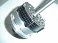
'fraid the pictures above are about as good as my camera gets.
Re testing, I was thinking of loading it with a bicycle disc brake/caliper & seeing if it gets warm with (say) a kilowatt going through. I can measure that via battery amps pretty well & use my cheapo thermal camera
Re testing, I was thinking of loading it with a bicycle disc brake/caliper & seeing if it gets warm with (say) a kilowatt going through. I can measure that via battery amps pretty well & use my cheapo thermal camera
bobc
10 kW
This is progressing OK. I want to run it in oil so I'm waiting on getting some thin gasket paper and I need some varying length M3 screws. I finally made the high speed axle right and the gear turns over reasonably well (with nothing tightened properly and a battery drill providing the motive power), I will laser the mounting brackets next week and build up the test rig. My plan is to run it in on the test rig under load for an hour or so then case harden the gears and rebuild properly.
It will be tried on a yellow painted skip rescue town bike.
The laser cutting actually cost me £20 (less than I expected), all the bearings were £45. The mounting brackets and chainrings will be another £30 or so (quite big 3mm stainless thingies). Add a scrap motor, a 6s Lipoly, a "mystery" ESC and a thumb throttle, I think this thing is looking within the range of many home engineers (essentially guys like me with a lathe in a shed).
The assembly (motor + gearbox) is very compact, there's plenty of room to extend the gears if it proves necessary (the left crank is missing the motor by over an inch). I saw a comment along the lines of "why look at cheap outrunners when the "astro" motors are so nice". When the next post on the forum was pointing out the cost of these things! You really do get astonishing bang per buck with the RC outrunners, cost per watt seems to be 10% c/w the astro. The key is making it driveable, which you can't really do with a modified servo tester (though in truth I have done thousands of miles with exactly that...).
Should get it spinning on load next week

SlowCo
1 MW
Looking good!
Curious of how it will perform and especially the wear rate. As is visible on the outside surface of the laser cut parts the roughness is quite high. Are the inner surfaces of the gears just as rough? Or did you manually remove the tops and smoothed the contact surfaces? I'm keeping my fingers crossed because if it does work and holds up for a reasonable time with decent power output this design is very promising!
Curious of how it will perform and especially the wear rate. As is visible on the outside surface of the laser cut parts the roughness is quite high. Are the inner surfaces of the gears just as rough? Or did you manually remove the tops and smoothed the contact surfaces? I'm keeping my fingers crossed because if it does work and holds up for a reasonable time with decent power output this design is very promising!
bobc
10 kW
Hillhater
100 TW
.?? Don't you trust gasket goo, Locktite, silicone etc ?
bobc
10 kW
yeah - I actually need to "find" half a millimetre or so, paper gasket is 2 birds with one stone.....
bobc
10 kW
No updates for a while - here it is together, not quite right yet but looks promising 
[youtube]_3Ux64ho4P0[/youtube]
BTW version 2 is already at the laser cutters...... it will be bigger (thickness 5mm and diameter 60mm) and I put needle roller bearings on the output drive pins to eliminate sliding contacts (as much as I can). I reckon version 2 should be pretty capable. I'll just use V1 as a testbench but V2 I think I will use for real.
SlowCo
1 MW
I'm glad you didn't listen to my doubts about laser cutting the parts... 
Nice result and I look forward to seeing this and the next version progress!
Nice result and I look forward to seeing this and the next version progress!
bobc
10 kW
I share your doubts Slowco, It's important to get this onto a bike pretty quick & subject it to some wear! I must say, for now the box feels pretty damn good, very positive, fairly smooth and no backlash. FWIW I actually think this method will work OK after case hardening & the bigger one will be OK up at the 2kW level. The laser cutting was so cheap it must make it a very attractive proposition to anybody with a lathe.
Hillhater
100 TW
Damm, ! That's impressive.!
Not just that you have a working prototype , but that it took less than a month from the initial idea and that you uses an unproven manufacturing process.
We are not worthy ! :lol:
Not just that you have a working prototype , but that it took less than a month from the initial idea and that you uses an unproven manufacturing process.
We are not worthy ! :lol:
Wheazel
10 kW
Fantastic project, looking forward to the posts to come!
bobc
10 kW
Here is the "taper lock" freewheel mount. I popped the motor stator on there as well  The 6 allen head bolts force a tapered 'olive' into the threaded part to squeeze the 20mm shaft, grips and centralises. The outrunner bell on the motor is held on a similar way.

The bottom bracket bracket is also on the bike now. The bike has a 68mm BB so I got a 73mm one (to account for the 2 thicknesses of 3mm stainless). You need to get the 118mm shaft to get enough room for the crank mounted freewheel (yes I have a 73 x 110 which doesn't work....)
Nice to see a bit of interest -
bobc
10 kW
Mmmm....No bellbottom pants riding that bike! 
Hillhater
100 TW
Bob, will you use a direct drive motor mounted on that input shaft (very slim ?)
..or a chain drive from a motor to the gox input shaft ?
..or a chain drive from a motor to the gox input shaft ?
AFAICT, the motor is already in the unit; I am pretty sure I can see the coils inside it in this image:

and I think it is the large cylinder off the right side of this image:


and I think it is the large cylinder off the right side of this image:
bobc
10 kW
Yeah HH, that slim 8mm input shaft replaces the motor shaft supplied within an ordinary outrunner
Hillhater
100 TW
By "slim" I was wondering if you had enough clearance to the crank ?
bobc
10 kW
Ahh, yeah with a motor that is the same size as the one linked above (6354) I have about 6mm spare with the cranks I bought and a 118mm axle. A wider axle is always possible if things turn out to be touching. That size motor has a 2kW headline so I'd expect a continuous 500W to be no problem, though I'll obviously be running this at 200W m'lud  I think the 2kW is a 1 minute rating.
bobc
10 kW
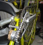
Mechanics is done now. You can see it's a motor with a lot of "history" & night not work - the "bell" is visibly slightly on the hoy; but it fits in the space provided & the cranks go round & it drives the back wheel nicely!
There's a bit of spring in the mounting when I try to turn the wheel backwards do I might have to do a little re-engineering here & there, but overall not looking too bad. Just the electrical bit to do now........

I'm afraid it's far from rivalling the "American beauties" - have you looked at the bike it's going on!!! And I'm aiming rough, cheap, DIY and EU legal. Can't wait to see how the gearbox performs though
There's a bit of spring in the mounting when I try to turn the wheel backwards do I might have to do a little re-engineering here & there, but overall not looking too bad. Just the electrical bit to do now........

I'm afraid it's far from rivalling the "American beauties" - have you looked at the bike it's going on!!! And I'm aiming rough, cheap, DIY and EU legal. Can't wait to see how the gearbox performs though
Similar threads
- Replies
- 206
- Views
- 14,593
- Replies
- 2
- Views
- 5,236
- Replies
- 93
- Views
- 37,304
- Replies
- 10
- Views
- 34,597


