CellLog 8 hacking

Connected an 8s to the CellLog, still no reading whatsoever.
What confuses me is that people mention errors like "cell error" or so if there is a problem with the analog part.

I rechecked the other 431 zener, all fine.
That is one path (though high Ohm) I could see for damaging the Atmel32 in case of polarity reversal, but I doubt it

The Op Amps deliver the same voltages (compared to a good CellLog I have) right to the A/D pins of the Atmel.

I cannot imagine the internal A/D to be bad, think this is some internal flash/configuration problem but have no way to test this.

Still stumped.
 
hillzofvalp said:
How would I use a multiplexer to change the cell groups the cell log checks? I know how it could work, but I'm unsure there is a multiplexer that would do it.. That way I wouldn't need 3 cell logs and 3 serial inputs on my arduino to monitor my pack.
Did anybody ever answered this question?
 
heathyoung said:
Sure, I have a version on the PC here I think.

For 7 cells, you just wouldn't connect to the cell 8 tap.

The input voltage range of the cell-log is 1.3-4.9V (and so is the alarm range). Obviously, you cant hook up a 12V battery to a channel, you would fry it!

So what to do... Divide it by 4. Use a resistive divider, with an opamp buffer (ie. gain of 1) powered off the 36V tap of the battery with a series zener diode of 6.1v (the opamp is rated for 44V max) . The reason for such a high voltage rail for the opamp is that the 8th output at 15V per cell (worst case) divided by 4 (3.75) and multiplied by 8 is 30V, and the opamp is not rail-to-rail, and so needs some headroom.

You get a voltage range of 2.5 (10.0V, dead empty for a 12V AGM) to 3.75V (15.0, highest cyclic charge voltage). You can use the alarm output to turn off your charger while the zener shunts (if you do this with your AGM's) do their thing, or warn you when you hit the LVC (or you have a single battery drop like a stone, or a massive imbalance occur - delta V).

The resistor values are calculated so that you have battery voltage/4. I have a PCB design around here somewhere as well.

At the highest voltage level (120V) the resistors will only be losing 0.9mA - and dissipating 0.1W.

Yes, you will unbalance the batteries eventually, but if you pulled from the whole pack voltage with an amplified zener reg, this would not be an issue. The dividers drop less than the self discharge rate anyway, so they are negligible.

Thanks for posting this heathyoung!

I am thinking of building one of these for my 96V lead acid pack (8x 12V flooded), and am looking at a few changes... Any comments / feedback welcome :)

1) Balance current draw on each battery by scaling resistor dividers. I'm looking at using these Bournes 4608X series resistor arrays as each has 4 isolated resistors of the same value, perfect for creating the 1/4 divider. They don't scale perfectly of course, so I'm simulating using the following for each tap: 1-4x10k, 2-4x20k, 3-4x33k, 4-4x39k, 5-4x47k, 6-4x56k, 7-4x68k, 8-4x82k. With that I get a current from each battery of between 0.33-0.39mA at the high end of 14.5V per battery. Max power in a resistor is ~10mW, well below the rating of 300mW per element. Ratios are still 1/4 everywhere as all 4 resistors in each divider are still same value (+/- 2%).
http://www.bourns.com/data/global/pdfs/4600x.pdf

2) Blow off zeners ;) As long as batteries are never hooked up in wrong sequence, it seems like these should be unnecessary. The op-amp inputs are tolerant of much higher voltage than the individual battery voltage. Any noise/spikes at the Celllog shouldn't really be any worse than when used on a Li pack?

3) Run op-amps off the full pack rather than 36V tap. Since it seems like the celllog will be powered off the op-amp outputs, I'd like to spread that over the whole pack. Was thinking of using an LTC3639 to regulate the 80-116 pack voltage down to 36V.
http://www.linear.com/product/LTC3639

4) Disconnect? Would be nice to add a switch to power down the monitor. I believe people usually cut the "gnd" line between the battery and celllog to reduce drain. Still trying to wrap my head around what would happen if you also cut the gnd connection to this circuit from the battery.

Any thoughts appreciated, will post schem and share results if I get something working :)

Rob
 
The CellLog gets it's power from the cells being measured, so if you place a resistor divider in series with the CellLog, the divider output will depend on the power consumption of the CellLog. If the power consumption remains constant, the divider can be built to compensate for this. There's a big difference between the backlight being on and being off, so you need to keep it in the same mode.

Alternately, the power for the CellLog could possibly be split off to a separate line and fed separately. This would prevent the divider load from changing. This would require removing D2 and R45 (actually a diode on mine).
 
Sorry, looks like the reply didn't link through to the original post:
http://www.endless-sphere.com/forums/viewtopic.php?f=14&t=20142&start=100#p579154

In heathyoung's original schematic in the post linked above, the resistor divider values are kept quite high to minimize the drain on the batteries, and op-amps in a unity gain buffer config are used to isolate the batteries from the celllog and provide the current to the cellog taps without skewing the divided down voltage.

My proposed changes are relative to his original schematic.

Rob
 
BTW, seems to be working out fine so far. This is just a prototype, but its correctly reporting 1/4 the voltage on each lead acid battery in an 8s 96V pack. I also verified that nothing funny happens when disconnecting the gnd pin from the whole circuit to power down. This should allow for nearly 0 current draw from the pack as it disconnects the resistor tree, powers down the op-amps, and the celllog is isolated form the pack so it can't draw anything on the battery taps.

So far the only mod from heathyoung's schematic is to scale the size of the resistor dividers for each tap (10k/30k, 20k/60k, etc) to balance current draw from each battery, using 4 equal resistors in an isolated resistor array for each tree/divider (ie 10k/30k is really 4x10k in series tapped at the bottom resistor), and the omission of the zeners. Powerup seemed to go fine, though I was careful to connect each battery in sequence and to the right tap ;) I bought parts for the 96V to 36V switching regulator to eliminate the 36V tap for the op-amps, but haven't built it yet.

Rob

photo-2-jpg.77641
 
way cool. you used those resistor DIPS for the bridges. that is like way cool.

those 8 DIPs span the entire battery voltage from top to bottom too. you have some circuitry on the low end of the pack it looks like. could not follow all of it yet.

i am thinking of something similar. the sticks in my insight battery are 6S of nimh and they measure up to 8.8V+ per stick so the cellog gives me the voltage error. outside the range.

i was thinking of how to make the battery into a 40S series of 3S nimh packs with each around 4.4V so i could monitor them with the cellogs. it is very difficult to get the voltage tap out to the outside of the battery from a position in the middle of the stick inside the middle of the battery case. the sticks are 6S long so i need a tap in the middle of the stick inside the case to connect each 3S to their own sense wire.

then i can use 5 of the 8S cellogs to cover the entire 120S nimh pack with resolution down to the 3S level, (40x3). that's my plan.
 
If you want to measure higher voltages, have you checked the PowerLog6s.
That one can do 0.05v - 28.0v per channel up to max 60v for the full 6 channels.
So u cant use it for 6 12v LA.
But 4 12v LA would work and 6 of those insight sticks would also work I guess.

Just saying.....

Regards
/Per
 
not familiar with them. if i could get 7 sticks under the 60V cap that would work to keep the total count down since there are only 20 sticks. i suspect the high voltage limit is based on the voltage limit on the regulator on the input so a hack of the input power may work on them.

do you have the data sheets?
 
They are only 6 channel, same producer as Cellog8

http://www.progressiverc.com/powerlog-6s.html

Check it out !

edit:
link to thread...
http://endless-sphere.com/forums/viewtopic.php?f=2&t=22792&p=341238&hilit=powerlog6#p341238


Regards
/Per
 
The resistor arrays worked out really nice. As I was hoping, it seems like the matching of the resistors within the array is much better than the +/-2% overall tolerance. So when you connect 4 in series, you get pretty high precision 25%, 50% and 75% taps for 33c per array :) I'm using 8 different values to roughly match the current, but when driven with the same source all 8 of the 25% taps were putting out the same Voltage to within <0.01mV.

I like the looks of the Powerlog, but didn't want to have to split my 8s pack across two monitors. For a larger stack where you have to split anyway, it might just make more sense to use the powerlogs.

Rob
 
BTW the rest of the circuit after the resistor dividers is just a series of 8 40V capable op-amps connected as unity gain buffers. They are powered off the 36V tap, but eventually I plan to add a switching regulator to power them off the whole pack. The op-amps basically just provide the bias current into the celllog taps, so that it doesn't skew the resistor dividers. Its basically the same as the schematic heathyoung posted on page 5, but without the zeners and using the resistor arrays instead of two different value resistors.

Rob
 
Also, not exactly a hack, but I was able to read the data out of the celllog using my mac. I just had to download the USB driver direct from the chip maker:
https://www.silabs.com/products/mcu/Pages/USBtoUARTBridgeVCPDrivers.aspx

Then I could connect to the port using CoolTerm, and read the data into a file for post processing in Excel.

Rob
 
miscrms said:
Also, not exactly a hack, but I was able to read the data out of the celllog using my mac. I just had to download the USB driver direct from the chip maker:
https://www.silabs.com/products/mcu/Pages/USBtoUARTBridgeVCPDrivers.aspx

Then I could connect to the port using CoolTerm, and read the data into a file for post processing in Excel.

Rob


Hm tying to set min up to use on my mac rather than the wife's windoz
What baud rate did you used. I've sen various posts saying its 128000 but mac does not ofer that.
Also tried dataexplorer and it too cannot connect at a valid baud rate.


Well answering my own question.. found that
http://forums.the-meiers.org/viewtopic.php?f=4&t=479
shows how to add non-standard baud rates to CoolTerm.. and with 128000 added I can get it to work and save files. Thanks for the pointer :lol:
 
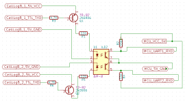
The following is a circuit to opto isolate multiple CellLog8 units along with the images of how to break out the VCC, GND and TXD from each CellLog8 and yes you could easily use a PC with 2 USB->TTL Serial Adapters in place of the MCU. A simple PC application could be written to monitor multiple serial ports and combine the data into a single log for testing purposes. The circuit only provides for electrical isolation to enable multiple cell log 8 units combined and attached to a larger series pack (my end design monitors 3 x cell log 8 units for up to 24 cells).

DualOptoIsolatedCL8.png

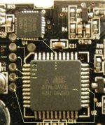
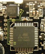
Every CellLog8 has TTL Level Serial cell logging output ability (both the M and S models) which is accessed by breaking out the GND, VCC and TXD as indicated above. I suggest sourcing the GND and VCC from the 6 pin ISP header (Pin1 and Pin6) and the TXD either from the test point indicated by the following image or directly from the leg of the chip (I go to the chip usually for TXD and the test point for RXD if needed).

CellLog8_ISP_Pinout_800x600.jpg

CellLog8_TTL-Serial_800x600.jpg

** LEAVE THE ISP port alone! Don't bother trying to dump the Flash and EEPROM they are protected and useless to us without the FULL CellLog8 firmware including the bootloader (which Junsi won't provide) or an open source alternative firmware (which doesn't exist at this time). Don't waste your time messing about with ISP, wasting your time is all you will be doing. To Flash anything (eeprom, flash, calibration, signature, etc), the whole ATMega32L MCU must be erased and when that happens we lose the protected bootloader and application code rendering the CellLog8 unit useless.
-William
 
Someone asked me via PM if I could provide the full schematic for isolating 3 x CellLog8 units and while I got lazy with Part Designators this Schematic PDF should explain not only how to isolate the CellLog8 units (3 of them, 4 is possible but requires use of base "Serial" or Uart0 of the 2560 Mega chip) but also how my MCU detects when a cell log is connected first (isolated trigger throws a digital input pin on the ATMega MCU to +5v upon connection which triggers a configure() routine), how I enable the logging output of the CellLog8 (by bringing the SW2 line out from the CellLog8 and sending it to it's respective ground in the configure() routine for 3 seconds via an optocoupler) and finally how I perform a full reset (digital output pin from MCU for each CL8 unit is sent logical high which brings the CL8 RESET pin from the ISP header to GND causing a "reboot".

View attachment CellLog8x3_FullSlaveCircuitSchematic.pdf

Yes there is a boat load of code to write for controlling this but anyone with even a mid level understanding of either c or Arduino IDE development should not have any issues. One point of note: If you use IVR INTERRUPTS for Serial IO, create a buffer array of characters with approx 60-64 bytes of space and collect the serial data byte by byte until the <CR><LF> is reached before processing the serial data within the primary loop, do not attempt to process this data within an Interrupt Handler.

Anyone with further requests feel free to PM me and if I have a circuit for it or can design one quickly it will be my pleasure.

Sincerely,
William
 
Quick question if anyone is reading this thread anymore and I'm not 100% wasting my time posting to it....

Does anyone have experience with http://www.ti.com/lit/ds/symlink/lm5008.pdf step down converter regulator IC, claim is good to 95v and I am looking for a more robust manor to power the MCU from larger packs than tapping the 5v rail of the controller.

Current in active mode is < 90ma and in standby its not measurable (with my equipment).

-William
 
I haven't used it myself, but there are a number of references in forum posts:
https://endless-sphere.com/forums/search.php?keywords=lm5008&terms=all&author=&sc=1&sf=all&sk=t&sd=d&sr=posts&st=0&ch=300&t=0&submit=Search
if any of htem are useful to you?
 
amberwolf said:
I haven't used it myself, but there are a number of references in forum posts:
https://endless-sphere.com/forums/search.php?keywords=lm5008&terms=all&author=&sc=1&sf=all&sk=t&sd=d&sr=posts&st=0&ch=300&t=0&submit=Search
if any of htem are useful to you?

Thanks that will work, just wanted to see the part in use before selecting it for a 100v-8.4v power source step down to run my MCU side of things I have a step down now but it tops out around 60v.

William
 
im still following this kind of stuff too.

currently im debating if I want my battery box to have a small window to show two cell-log 8m units at a push of a button(16s lipo).... but like most people, I worry about it pulling the cells out of balance. they stay pretty well balanced as they are right now.
 
Are people still using these for Lipo cell LVC for pack or throttle power? There seems to be more inexpensive mini smart BMS boards on the market now than a few years ago. For example

https://bmsbattery.com/bmspcm/330-smart-bms-513-cells-in-series-bms-pcm.html

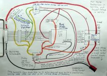
The reason I'm asking is because I finished a simple circuit that can monitor and cut-off pack power as well as power to the cellog itself if you forget to turn off the main power switch after a ride.

Its not perfect, but my daughters battery survived a 6 month winter of neglect without having any damaging buzzer drain, without unplugging the buzzer. The circuit simply cuts off pin 1 power when the cellog alarm is triggered, or when the power switch is turned off.

My idea was to treat each battery independently and give it a cut-off circuit and power relay; like how a power tool Lipo cuts itself off. The circuit uses a signal relay to cut off power to the buzzer on alarm, which then turns off the power relay. Then multiple 2-8S LiPos can be but in series. I did this because I didn't want to deal with more complicated circuits with optocouplers or trying to balance buzzer drain over multiple LiPo Cells.

Here is a hand diagram in case anyone else is interested in doing this:

Lipo-LVC-Cellog-Relay-Circuit-1280.jpg
 
pa.hioficr said:
The following is a circuit to opto isolate multiple CellLog8 units along with the images of how to break out the VCC, GND and TXD from each CellLog8 and yes you could easily use a PC with 2 USB->TTL Serial Adapters in place of the MCU.
This is very interesting!
What would I need to connect the CellLog to an ESP8266 module, which is powered at 3.3V and is full-compatible with Arduino?
This would allow connecting Celllog to cellphone and to internet/cloud! :D

As far as I can understand, I could also use the cheaper CellLog8m for serial connection, isn't it?
 
I post an exaggerated-resolution image for better understanding/hacking :wink:
(I slightly edited it by merging multiple pictures with different light conditions)

https://jumpjack.files.wordpress.com/2016/11/celllog-pinout-ann.png
 
Back
Top