Compact Field Oriented Controller, ASI + Grin, limited run

district9prawn said:
Interestingly, the phase runner is giving me the same problem the bac500 did before it got a firmware update. There's a bit of stuttering under light load, which can sometimes result in over current faults. Under WOT it is usually fine. The motor still spins smoothly under no load, but will start hiccuping under light loads. The firmware update in January for the BAC500 fixed this completely and I never managed to replicate the issue even if I played around with the PI loop values. For now, I can reduce the current regulator gains which helps a little but by no means solves it.

Can you clarify two things:
a) What motor you are using (geared vs direct drive, effective pole count, and winding resistance + inductance), and also
b) Did you first save the original parameter file that was working fine before you did the calibration fix, and then reload that identical parameter file back on the device? Or did you just do the calibration patch and then attempt to recreate your original tuned settings manually.
 
justin_le said:
district9prawn said:
Interestingly, the phase runner is giving me the same problem the bac500 did before it got a firmware update. There's a bit of stuttering under light load, which can sometimes result in over current faults. Under WOT it is usually fine. The motor still spins smoothly under no load, but will start hiccuping under light loads. The firmware update in January for the BAC500 fixed this completely and I never managed to replicate the issue even if I played around with the PI loop values. For now, I can reduce the current regulator gains which helps a little but by no means solves it.
Similar issues for me, although in my case it’s not clear that it’s related to the fix. My unit faulted 3 times today, all under what I would consider undemanding conditions. Twice this morning before I applied the fix, and once this evening after I had applied it.

Starting torque still seems very sluggish. And I have a steep hill on my ride home that was noticeably slower today than on my previous ride before I had applied the fix.

Can you clarify two things:
a) What motor you are using (geared vs direct drive, effective pole count, and winding resistance + inductance), and also
b) Did you first save the original parameter file that was working fine before you did the calibration fix, and then reload that identical parameter file back on the device? Or did you just do the calibration patch and then attempt to recreate your original tuned settings manually.
My motor is an 8-turn Mac. I entered the parameters as actual pole count (16 pairs) and actual motor RPM (2900) and gear ratio (5). Ls = 51 uH and Rs=33 mOhm

I saved and reloaded my pre-fix settings without doing any re-tuning or manual parameter changes.
 
justin_le said:
a) What motor you are using (geared vs direct drive, effective pole count, and winding resistance + inductance), and also
Motor is a cyclone with planetary head. 4 pole pairs. Motor discovery claims 95 mohm and 44 uH. I'm fairly sure most of these basic values along with the sensorless parameters are fine since I'm using the same on the BAC500 with great results.

justin_le said:
b) Did you first save the original parameter file that was working fine before you did the calibration fix, and then reload that identical parameter file back on the device? Or did you just do the calibration patch and then attempt to recreate your original tuned settings manually.
I loaded from file after the fix.

I'm curious now what the difference is between the two bac500 firmware versions.
 
Hmmm... The new firmware/bootloader makes the voltages read properly but has introduced a new issue where something errors out if I come off the throttle too quickly. Can we have the old '.ehx' file to run with for now (understanding that it has voltage calibration issues)?

Edit: I've made too many changes to definitively say that the new .ehx was the cause of the issue, but it has happened at the same time.
Edit 2: The problem seems to be something related to my super-cheap china throttle and having the CA plugged in. Works fine with no CA :roll: .
 
District9prawn, I measured the inductance and resistance of the cyclone 1680W and got 154uH and 60 mOhm (73 mOhm with leads) I don't know if that will help anything.
 
Ok so loading my xml parameter file from my bac500 seemed to let the phase runner work smoothly without stuttering or hiccups under various loads. I have no idea what settings made the difference as the settings for both motors look pretty darn similar!

Also my CA shows peak battery current at 55A :D . That could be 3kw for those running higher voltages.
 
More unusual behavior-- the controller is no longer spinning the motor at full RPM unloaded, and if I up the rated motor RPM value the reported motor RPM value goes to something like -130. Byte overflow or maybe some sort of signed/unsigned error? This is with version 1.5.4 of BACDoor.

My implementation is a bit (read:completely) different from an ebike, I'm running at around the 2-3k rpm range while loaded (or at least I need to be). It was able to run the motor at about 2300 rpm before, but now am only able to run it at about 1100rpm unloaded. Wondering if the software/firmware wasn't written to handle this since it seems to be marketed mostly for ebikes.
 
Wonder how the Phaserunner will work with a MAC 10T....

I have a feeling the softer wind up on the pulse may quiet things down a little bit. More gradual blips of thrust may extend gear life a bit.

Looking forward to playing with it.
 
Triketech said:
Wonder how the Phaserunner will work with a MAC 10T....

I have a feeling the softer wind up on the pulse may quiet things down a little bit. More gradual blips of thrust may extend gear life a bit.

Looking forward to playing with it.

While we're wondering about things... anyone want to take any bets on me having issues with it driving a stock 80-100? :mrgreen:
 
Well, mine finally came!
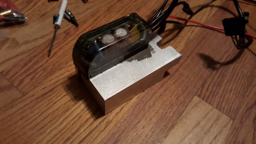
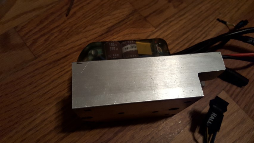
Since I havent seen anyone do this yet... heres what it looks like when you get it.
Really I was planning on taking pictures the entire time I was putting it together, but once I started swapping the connectors to plug into my setup, I forgot to take anymore pics. :lol:

20150817_191254.jpg

20150817_191332.jpg

20150817_191344.jpg

20150817_191459.jpg

20150817_195020.jpg

20150817_195027.jpg

20150817_195035.jpg


The big chunk of aluminum bolts to my scooter and acts as a spreader to the aluminum chassis that is out in the airflow. It also makes a decent heatsink itself to even out small peaks.

MrDude_1 said:
While we're wondering about things... anyone want to take any bets on me having issues with it driving a stock 80-100? :mrgreen:

Now on to the less fun stuff... I am running a 80-100 in sensorless mode with this controller. I followed all the directions listed in the thread, and it works great... with no load.
So I took it outside and went down the street. At lower speed it pulled off smooth. there was a bit of a lag on throttle input, but I need to reset the CA to not ramp the throttle... I think thats the problem.
I went down the street fine, but on the way back, I decided to go a little faster. It accelerated smoothly, and then suddenly snapped off. (not the best feeling when you're balanced on a board doing an estimated 30mph)

I coasted most of the way back home and hooked up the controller. "instantaneous phase overcurrent fault".. uhh. ok. So I spent a good 45 mins looking around in BACdoor.
I got nothing. I cant find where to set the fault limit for Phase current, or how I am supposed to stop it before it gets to an overcurrent state.
I think my real problem is I dont understand the error.
Is it saying the motor is drawing too much current? I thought it was supposed to limit it to what I put in (entered 100A, but it changes it to 96A)
is it saying the back EMF of the open phase is too high? Because I thought that was also limited to less than, but similar to what it was putting in.
is it saying something totally different?
Finally, why does it only happen at high speed? I expect any current limit to hit when pulling away from a stop. I think I am misunderstanding the error.


I attached my BACdoor setup below. I am running the newest version.

Setup on the scooter is:
16s 20ah lipo (66v as ridden) -- rated to 400a draw, with 400a capable connectors, but I never pull more than 100a on it.
80-100 motor, running sensorless
Cycle Analyst V3 running the throttle/everything.... also the CA is showing a 7w draw even when the scooter is not being used, but I havent looked to see if that is the frequency draw from sensorless, or if shunt is incorrectly calibrated or if its something else.

I also watched the controller voltage on the laptop and its 100% spot on for my battery. No voltage calibration issue there.
 

Attachments

  • 80-100 settings.xml
    26.7 KB · Views: 178
AH HA!!! I am stupid. I have the poll pairs at 7, but its supposed to be 6!!!
I will go mess with this as soon as I get home at lunchtime. :pancake:

if anyone sees anything else wrong with my setup, please speak up. I am still here for the code mocking.

dt130224.jpg
 
Ok, just got back from lunch, and I played with it a little more. Did you know that if you disconnect the laptop from the controller, BACdoor will not let you save it on your PC? It also wont let you open a file unless you have a controller connected. So I dont have my "new" file...

I should note: I fixed the 7 to the 6 it should be... but it didnt matter.

I set a couple amp limits higher, and I stopped throwing the code... I set the Overload Continuous Current to 200% and it didnt seem to change anything. so I set the Instantaneous over current trip threshold high, and the controller output current rating higher. how high, I dont know as I couldnt save the file.

This did change the behavior. I no longer required a reset... instead I would ride under a heavy load, and it cut out like before. if I let off to zero throttle then rolled it back on, it would work again.
better, but still having the throttle randomly cut off sucked.

I brought it back into the garage, and propped the wheel up. I found that if I nailed the throttle and held it there, it would cut off.
So then I had the thought that the CA may be cutting the throttle off.... overcurrent or some other trip... So I set it to pass through, and I set the max battery amps to 130.. plenty high for the phase runner.
Heres what I set it as: View attachment PhaseRunner pass thru.hex

AND..... it behaved the same. I couldnt believe it. I thought for sure it was the CA cutting it off and resetting.
When I connect to the controller now, there is no fault code. it just cuts off until throttle goes back to zero.


Next step, when I get home is to have the controller log the throttle voltage, rev it until it cuts out, and then see if the throttle voltage changed indicating its the CA, or if its the controller... unless the log of throttle voltage is a calculated value that reads zero under a fault, in that case it wont help.

Anyone have any other ideas?
 
your magnet pole count is 7 (14 magnets)
the stator tooth count is 12.

I won't be much help for a day or two, raining HARD & supposed to continue all noght & tomorrow too.

where did you start on battery limits?
I am not plugging a CA into just yet...straight throttle set up.
I will be benching some stuff tonight.

thanks for keeping us current (there's a pun in there somewhere)
T
 
Thud said:
your magnet pole count is 7 (14 magnets)
the stator tooth count is 12.

I won't be much help for a day or two, raining HARD & supposed to continue all noght & tomorrow too.

where did you start on battery limits?
I am not plugging a CA into just yet...straight throttle set up.
I will be benching some stuff tonight.

thanks for keeping us current (there's a pun in there somewhere)
T

Ok, so I WAS correct the first time... 14poles, for 7 pairs. I thought it was 7, but when I re-counted from pictures when I took it apart, I got 12. :lol:
So I'll change that back. Hopefully that is what was making it lose sync or whatever whats cutting it out.

Battery limit, I forget where I set it, but it was high. If you take my XML file above (with the phase runner connected) you can open it and view it. Just dont write it to the phase runner unless you want to run the same setup as me. lol. When its at 65.0, you can pull a solid 80A from it and it will only sag to 63.8... so its pretty strong.
The intent on my setup is let the controller run as much as it wants/can.. just using its thermal rollback if it gets hot. I am not limited by the battery or the motor, just the controller. So whatever It can give me is good. My understanding of the PhaseRunner is it will roll back the phase current as the MOSFETs heat up... so if I am at max draw I may slow down just like a battery dropping voltage. If It keeps getting hot, I can make a new lower pan and run a huge heatsink with direct airflow... however most of my riding should be full speed, not stop and go, so I expect the draw will drop to what it can reasonably tolerate.

As far as bypassing the CA, I cant easily do a straight throttle setup without taking everything apart... but if I keep having issues, I will. I just cant ride it that way. throttle cable is only 3" long because its normally right next to the CA.


I really am rushing on this a bit, I would love to ride it to and from work... but remember that "no free time" thing we were talking about.. Im starting one of those crunches myself, and I really want this done now, instead of 2 months from now. The weather here isnt helping either. lol.
 
MrDude_1 said:
Next step, when I get home is to have the controller log the throttle voltage, rev it until it cuts out, and then see if the throttle voltage changed indicating its the CA, or if its the controller... unless the log of throttle voltage is a calculated value that reads zero under a fault, in that case it wont help.

Anyone have any other ideas?

Are you running sensored or sensorless?

Double check your rated RPM is appropriate for your voltage, and that your Rs & Ls terms haven't changed for some reason.

After that, it's time to start playing with the current regulator bandwidth. I found high RPM and low inductance motors would sometimes trip the inst. phase overcurrent loaded or not until I tuned the current regulator. If the bandwidth adjusting is helping, but not fully solving your problems, head into Controller Debug and play with the regulator Kp and Ki terms.

What speed regulator mode are you using? I'd use Torque (1)

Hope this helps
 
robbie said:
Are you running sensored or sensorless?

Sensorless.


robbie said:
Double check your rated RPM is appropriate for your voltage, and that your Rs & Ls terms haven't changed for some reason.

I did alot of research on here about my motor. Several years ago it was popular on here, so theres alot of info.
The sticker on it says 130kv
On a trapezoidal controller its around 145kv
On a sinusoidal controller its around 137kv
On other FOC controllers its around 135kv
So I put it in as 135kv * my battery rating of 67.3 and got 9000rpm.. i started with that.
Later I did a autotune, and it gave me 10,000 something RPM... however that was after I mistakenly changed the pole count to a 6.. once I change it back to a 7 I'll reset it and do an autotune again to get a true Kv/RPM. Is this an acceptable way to do it?

I will do the autosense for Rs & Ls a few times to make sure they stay consistent. However they didn't change yesterday when I did it multiple times, so I have confidence in them.

robbie said:
After that, it's time to start playing with the current regulator bandwidth. I found high RPM and low inductance motors would sometimes trip the inst. phase overcurrent loaded or not until I tuned the current regulator. If the bandwidth adjusting is helping, but not fully solving your problems, head into Controller Debug and play with the regulator Kp and Ki terms.

Thanks... Its good to know what numbers I should be messing with... however I have no idea what these terms are or what they do. Can you give me a bit more explanation of what the "current regulator bandwidth" is?
also, the Kp and Ki... what are they in the loop? I am a programmer so I understand basic logic if you have a block diagram or something.
Under controller debug->control loops I see "current regulator bandwidth" is this different than the one on the peripheral config - > basic motor (sensorless) tab?

sorry for all the questions, I just need to wrap my head around this. I know this default setting is more for large hub motors at 24-48v.. not large scale RC motors at 66v

robbie said:
What speed regulator mode are you using? I'd use Torque (1)

I am using Torque. Its one of the cooler aspects of this controller. I prefer it over every other throttle scheme. easier to relate in my head after years of motorcycles.


robbie said:
Hope this helps
it does, it gives me an idea of the numbers I should be playing with.. I have some base knowledge of how these motors work, but this is a bit of trial by fire for me. Ive never had advanced controller options infront of me.
 
Lebowski said:
'Back emf of open phase too high' ? Is it a FOC controller which powers only 2 out of 3 phases ? Is that even possible ?

Thats was what I was thinking the first time I read the error. lol. HUH? How? :lol:
 
It's probable that your eRPM is a bit high for smooth operation without some fine tuning.

9000 RPM @ your voltage * 7 pole pairs - 63000 eRPM is a bit higher than the conservative limit of 36000 eRPM. I also have notes that the recommended inductance limit (low side) is 50uH - and that users might experience over current trips due to this. What was your inductance as per the autotune? If it's low, you may want to consider adding inductance chokes to your phases (do this after trying to tune using the bandwidth or Kp Ki).

If you want to use Auto Generated Kp and Ki terms, the controller will use the inductance and resistance of the motor, along with the current regulator bandwidth to determine these values for it's control loops. Start with lowering the phase current and lowering the bandwidth.

Alternatively, you can go straight to Kp and Ki tuning, and follow classic tuning methods (set the regulator bandwidth to 0 if you are adjusting current Kp and current Ki).

I'm pretty sure when I was checking into the eRpm limits, I had to manually adjust the Kp and Ki to get stable results. I'll grab my notes from that and get back to you.
 
robbie said:
It's probable that your eRPM is a bit high for smooth operation without some fine tuning.

9000 RPM @ your voltage * 7 pole pairs - 63000 eRPM is a bit higher than the conservative limit of 36000 eRPM. I also have notes that the recommended inductance limit (low side) is 50uH - and that users might experience over current trips due to this. What was your inductance as per the autotune? If it's low, you may want to consider adding inductance chokes to your phases (do this after trying to tune using the bandwidth or Kp Ki).

If you want to use Auto Generated Kp and Ki terms, the controller will use the inductance and resistance of the motor, along with the current regulator bandwidth to determine these values for it's control loops. Start with lowering the phase current and lowering the bandwidth.

Alternatively, you can go straight to Kp and Ki tuning, and follow classic tuning methods (set the regulator bandwidth to 0 if you are adjusting current Kp and current Ki).

I'm pretty sure when I was checking into the eRpm limits, I had to manually adjust the Kp and Ki to get stable results. I'll grab my notes from that and get back to you.

lol at my inductance.. autotune says its 12uH. Ive been using that number.
Im actually cleaning up in the garage right now, but after messing with it for a bit, not knowing what the bandwidth does, I dropped the number lower and lower... didnt help.. so I raised it up to 1300 and it worked. so far.
I still have no idea what that setting does, and that makes me nervous. I have a few years of tuning cars via laptop software.. and you really need to know what you're doing there. Here I feel a little safer money wise, but I still REALLY dont want to let any magic smoke out. :lol:

is there any reason 1300 will not work?
I autotuned my motor over and over, for inductance and resistance... 12uh constantly, but resistance would swap between 12 and 15mOhms... never 13 or 14. I went with 12-12 for both.
 
No - as far as I recall the higher the bandwidth, the faster the system will respond, I recall setting my geared eZee motor to a bandwidth of 3000 to get it running well.

12uH is really low.. haha wow.
 
mjayt said:
So everything in the setup instructions makes sense for the bac2000 except the green throttle wire coming from the CA3 and what to do with the yellow wire from the CA3. I see in the picts that there is a red wire in pin 4 that is connected to what looks like a resistor that is connected to the green wire that goes to pin 6 or the throttle. What is the purpose of this 5v+ wire, do I really need it and if so what is the spec on the resistor....1ohm? Is there a set of instructions I missed in the CA setup?

Hey mjayt, there are actually a number of ways to set things up here and the way that was pictured is a more complicated approach that has a both a throttle plug and a CA plug that is both CA2 and CA3 compatible. If you are planning just to use a CA3 and never a stand alone throttle and CA2 device, then all you need to do is hook up the green throttle output of the CA3 to either the throttle input or ebrake input of the BAC2000 (software will let you choose which signal you read from).

So the yellow wire from the ca is for sp or speed right? I am using the wheel mounted magnet sensor for speed input. Does that mean I do not need to connect the yellow wire to anything?

Exactly. In that case there is no need to connect the yellow wire to anything.

I should mention that I am not running a throttle from the controller. The throttle is being controlled by the CA3. I think that diode or resistor, or what ever that is on the red wire is for the controller throttle on your shop setup in the pic, thus i don't think I need it. I think I just need to run the CA3 green wire directly in to the pin6 slot, but wanted to make sure that is what I needed to do before execution.

You've got it correct.
I am also running sensored unlike the posts pictured setup. So could I run the yellow wire to one of the hall wires, or is that redundant due to the fact that I have a wheel magnet sensor already setup to the CA3?

You could do this if you wanted to eventually get rid of the wheel magnet sensor and convert your CA3-DPS into a CA3-DP device, but then it limits you to using sensored hub motors for the speed readings. So if you have the CA3-DPS with external speedo, I'd just leave it as is.

I've also attached a draft .PDF document that has the wiring schematic for hooking up the BAC2000 to have a direct plug Cycle Analyst port on it, which should be a bit more clear than the earlier photos.


also is it possible to wire the blue and white wires into the controller shunt instead of using the 1ohm external shunt you have pictured. would you point out where the controller shunt is on the controller circuit board?

I am running a HPC Striker(HPC Modified crystalite v4) with a drilled motor cover for ventilation. I also has a linear temp sensor that is running to the CA3. the battery is a HPC limn 96v 65a 13ah that is pushing the bac2000 that is running strictly as a slave device. this is all setup on a Montegue paratrooper 2012. I too will post my config settings from bacdoor when all is configured.[/quote]
 

Attachments

  • BAC2000 Controller.pdf
    2.2 MB · Views: 145
Back
Top