Compact Field Oriented Controller, ASI + Grin, limited run

I set everything up on the bike and after an hour of cable routing and zip-tying, I got no power and a flashing LED.

Did you save your parameters to flash? I had only clicked write the first time I set it up but evidently that doesn't save the parameters to non volatile memory. So I had a flashing fault code. Had to redo the setup.
 
Grizzl-E said:
Did you save your parameters to flash? I had only clicked write the first time I set it up but evidently that doesn't save the parameters to non volatile memory. So I had a flashing fault code. Had to redo the setup.
Thanks for the idea, but yeah, I did save to flash.

Just had a chance to play with it a little more - turns out it runs fine with the wheel off the ground. But any torque at all on the wheel, even just the weight of the bike without me on it, and it cuts off the power. When I watch the currents as I apply the throttle, I can ramp up the motor current to about 10 A while holding the bike still (this takes almost no effort), then the current spontaneously goes to zero. The battery current at this point is something like 0.1 A.

The behavior is the same whether I have it in hall-only or hall-start mode.

For what it's worth the balance-of-system is an 8-turn MAC and 12s 10 Ah Multistars.

Guess I need to play around with some current thresholds and try to get a handle on this per-unit business...
 
Oh ya, had that happen too. Check your anti stall time. Default is ~200ms. I changed mine up to 2000ms (2sec). Worked great after that.
 
Grizzl-E said:
Oh ya, had that happen too. Check your anti stall time. Default is ~200ms. I changed mine up to 2000ms (2sec). Worked great after that.
Thanks, that actually enables me to get out of the driveway and limp around the neighborhood. I'm still having issues that I think are related to running a gearmotor - freewheeling, clutch engagement, etc. The drive is jittery when i re-engage after coasting, and if I don't immediately back off the throttle, it faults out and I have to hop off and disconnect the battery.

I'll update after I've had more time to work on it tomorrow. Anybody running a gearmotor that has run into similar issues?
 
cycborg said:
toolbag said:
Got mine in yesterday and it looks great! My one concern is that it is displaying a different voltage on the DC bus in BacDoor than I see with a multimeter. Is there some sort of scaling factor I need to apply in BacDoor for this? I've been powering it with a mean well RSP-750 at 48V and the software is telling me I'm at 41V.
Same here. Multimeter says 48-49, PhaseRunner says 39.

Whoops, it looks like we may have some of our testing operations in manufacturing using a setup parameter file originally made from the BAC500 units which changed a voltage calibration value. Will look into this and get back shortly.

Just a suggestion...Host a repository for user configurations so people can easily find a config for their specific motor and/or upload their own tweaked config so the best possible configurations for specific motors and uses will filter down through the community.

Yeah I think that's a great idea and something like this will be in the works, and in the meantime people feel free to upload successful setting configs here.
 
cycborg said:
I'm still having issues that I think are related to running a gearmotor - freewheeling, clutch engagement, etc. The drive is jittery when i re-engage after coasting, and if I don't immediately back off the throttle, it faults out and I have to hop off and disconnect the battery.
OK, I dialed the current regulator Ki way back and it seems to be stable now (was ~70, I set it to 10). Initial acceleration still seems a little sluggish so I tried boosting my motor current limit from my original setting of 60 A to the maximum of 74 A, but this caused similar faults so I left it at 60 A for now.

Whoops, it looks like we may have some of our testing operations in manufacturing using a setup parameter file originally made from the BAC500 units which changed a voltage calibration value. Will look into this and get back shortly.

...

in the meantime people feel free to upload successful setting configs here.

Makes sense; and hopefully with proper scaling I'll be able to tune the acceleration up without introducing instability. I'll post my settings here when this gets sorted out on both ends.
 
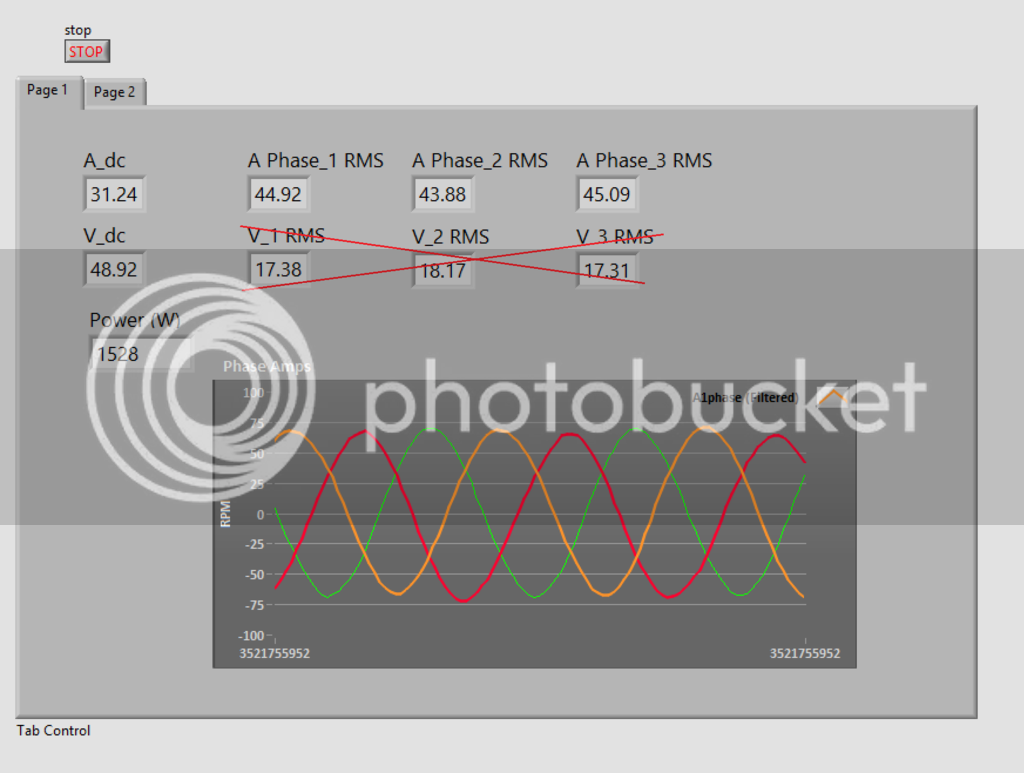
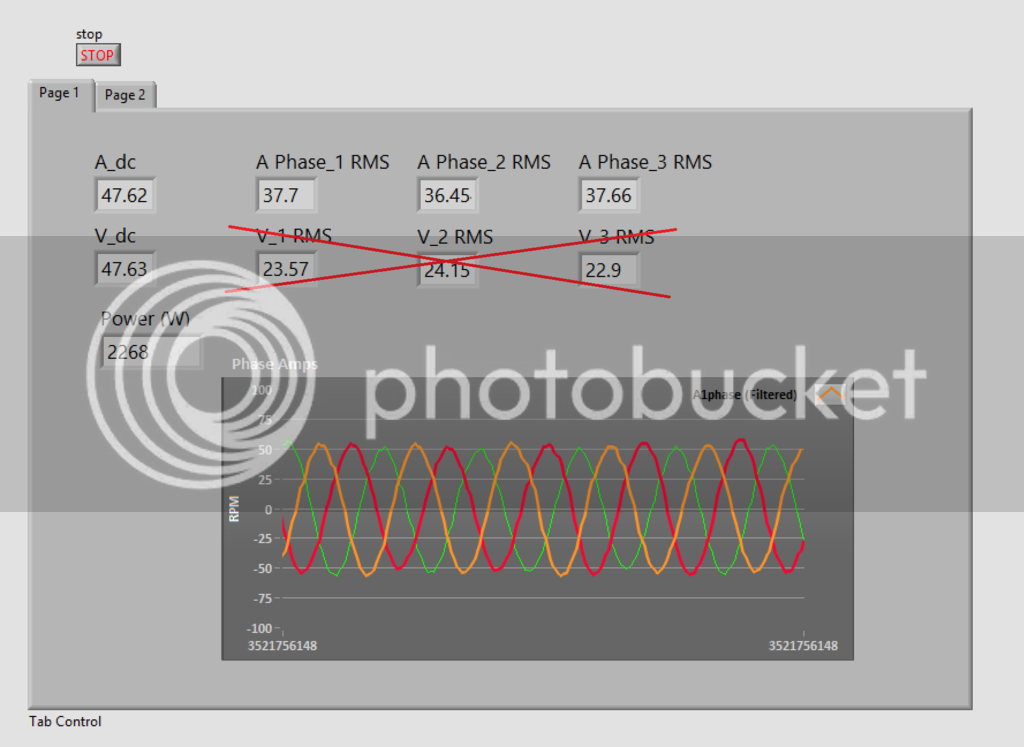
Ran some more tests today and it's looking awesome!

Screenshot%202015-08-06%2018.32.32_zpsntnbhp3d.png

(ignore the phase voltage readout, it's wrong)

Screenshot%202015-08-06%2018.35.48_zpshv1qmke0.png


It looks like it's happy to run at 2.3kW for a long time, though the controller did get too hot to touch. It was indicating 50C at that time, so I'm concerned that the temperature feedback isn't representative of the actual peak temperature :? .

Looking forward to getting that DC bus voltage calibration sorted out.
 
This is really cool to see. I love data like that and looking at the amperage for 3 phases then the DC amperage to compare so cool.
 
cycborg said:
OK, I dialed the current regulator Ki way back and it seems to be stable now (was ~70, I set it to 10). Initial acceleration still seems a little sluggish so I tried boosting my motor current limit from my original setting of 60 A to the maximum of 74 A, but this caused similar faults so I left it at 60 A for now.

I had 'bit 9' phase over-current issues when I set the 'Rated motor power' under 'Motor Nameplate Ratings' too high. It works for me set at 3kW when running up to 2.3kW. When set at 4kW and above it errors out when I throttle up.
 
Well, the amber PhaseRunner had its first real ride today, my 10-mile, 30-minute commute, including plenty of stops and starts and hills. I was very pleased with how smoothly it performs, and how intuitive the torque throttle is compared to PWM throttle.

I was also pleasantly surprised at how much quieter the motor is - I figured the FOC would reduce the torque ripple and the associated noise, but I figured I was stuck with the gear-related noise. But I literally can't hear it over the wind in my ears at 30 km/h except going up hills.

I'd still like more punch in the initial acceleration, so I'll try to tune that in a little more. But I prefer the slower acceleration to the jolt I'd get when engaging my PWM controller which apparently lacks phase current limiting. Ideal would be somewhere in between. :wink:

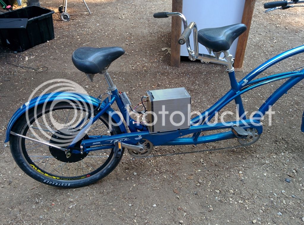
Some photos. First, the wide view of my EZ-Speedster. You can just see the PhaseRunner mounted on the horizontal tube behind the seat.


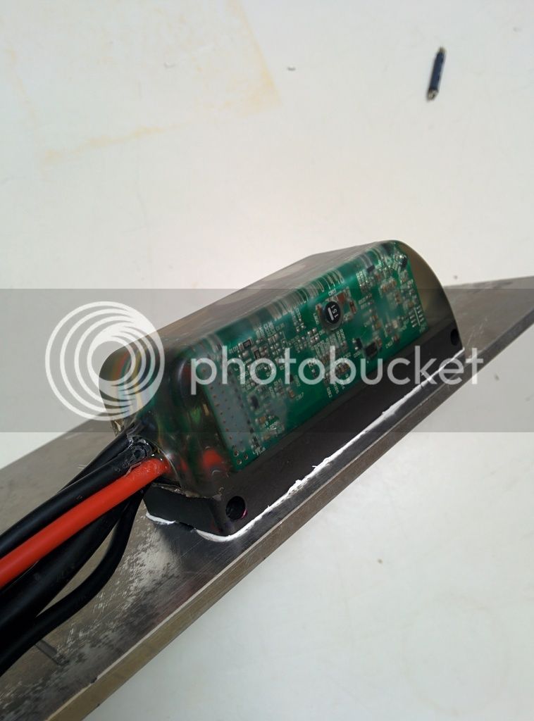
Here's a close-up of the exquisitely engineered mounting and heatsinking. Okay, it's zip-tied to a tube. :roll: But fortunately it's a square tube so the thermal interface should have a decent surface area, and most of the time I'm running below 500 W.


Here's more of a top view that shows some of the cable routing. Yeah, that bundle down there is a little ugly. I'll figure out something when I have more time.


Thanks to ASI and Grin for getting this little gem into our hands, and thanks all for your suggestions to help me get it running! :D
 
cycborg said:
I was also pleasantly surprised at how much quiter the motor is - I figured the FOC would reduce the torque ripple and the associated noise, but I figured I was stuck with the gear-related noise. But I literally can't hear it over the wind in my ears at 30 km/h except going up hills.
I wonder if some of the gear noise is from the torque ripple itself?
 
amberwolf said:
I wonder if some of the gear noise is from the torque ripple itself?
Undoubtedly some of the torque ripple is transmitted through the gear train, but even with a perfectly uniform driving torque, you'll still have gear meshing noise.
 
cycborg said:
Some photos. First, the wide view of my EZ-Speedster. You can just see the PhaseRunner mounted on the horizontal tube behind the seat.

Awesome, thanks for sharing the pics Cyborg. The flat tube like that is just ideal for using the bike frame to suck the heat out, and a bit of thermal paste between the two might not hurt. It's really nice to hear about the noise reduction on the geared drives too. We observed that on the few gear motors we tested on but haven't done much extensive riding with too many setups.

For everyone else, there will be a large batch of Phase Runner shipments going on the door on Monday. We held off shipping them while sorting out the voltage calibration error that is on some of the units, and will also have a formal fix for that early next week too for those who got a device that reads voltages about 15% low (the currents are also going to be reading a little low on those too).
View attachment 1

So far we've had mostly clear orders but there has been asides from the amber, at least one red, one blue, one green, and one black in the mix.
Red and Blue.jpg
For fun we've added one more choice called "surprise me!" from the dropdown for anyone who wants to see a more psychedelic pour with multi coloured layers and sparkles or who knows what. The ladies in manufacturing are fine art students and are dying for a chance to have a bit more creativity :)
 
justin_le said:
For people who ordered the larger BAC2000 units, you'll obviously need to prepare an appropriate cable harness that includes a pinout of either the TTL level or RS485 level communication leads. Here's an example of how we did a simple harness that has a throttle plug, a 6-pin CA plug (V2 and V3 compatible), and the TRS jack for communication with the standard CA programming cable.
View attachment 1

The phase and battery leads hook up with screw down terminals inside the housing cover. On the battery lead, we have a 1mOhm inline shunt resistor crimped to the cable, with the black, blue, and white CA-DP plug wires soldered to it. It's covered in shrinkwrap in the photo unfortunately. And you'll notice that there are some extra thinner gauge red wires on the V+ battery lead. One of these is for the Cycle Analyst V+, and the other is for the key switch input on the signal plug.

You must connect the Key-In line to the battery V+ voltage in order for the controller to power up, since that supplies power for all the logic and control circuitry.

View attachment 3
For the 16pin Molex Connector, the pinout from the datasheet is as follows:
View attachment 4

We've found that rather than using the pin7 Throttle Input, it's more convenient to hook up the throttle signal line to pin 6, the analog brake input. In the BACDoor setup utilty, you can then choose your throttle signal source to be the analog brake input line, and then again map this so that you have throttle signal from say 1.2-4.0V, and have regen mapped to start at 0.8V and go maximum at 0.0V, and then you'll have proportional acceleration and braking with a single wire. Of course if you have separate analog throttle and ebrake signals on your vehicle, then each should use the appropriate pin.
View attachment 2

Hope that's enough to get people started.

So everything in the setup instructions makes sense for the bac2000 except the green throttle wire coming from the CA3 and what to do with the yellow wire from the CA3. I see in the picts that there is a red wire in pin 4 that is connected to what looks like a resistor that is connected to the green wire that goes to pin 6 or the throttle. What is the purpose of this 5v+ wire, do I really need it and if so what is the spec on the resistor....1ohm? Is there a set of instructions I missed in the CA setup?

So the yellow wire from the ca is for sp or speed right? I am using the wheel mounted magnet sensor for speed input. Does that mean I do not need to connect the yellow wire to anything? Or do I need to connect it to a v+ source? It looks like the yellow wire in the picts is connected to something but can not tell what that would be.

I should mention that I am not running a throttle from the controller. The throttle is being controlled by the CA3. I think that diode or resistor, or what ever that is on the red wire is for the controller throttle on your shop setup in the pic, thus i don't think I need it. I think I just need to run the CA3 green wire directly in to the pin6 slot, but wanted to make sure that is what I needed to do before execution.

I am also running sensored unlike the posts pictured setup. So could I run the yellow wire to one of the hall wires, or is that redundant due to the fact that I have a wheel magnet sensor already setup to the CA3?

also is it possible to wire the blue and white wires into the controller shunt instead of using the 1ohm external shunt you have pictured. would you point out where the controller shunt is on the controller circuit board?

I am running a HPC Striker(HPC Modified crystalite v4) with a drilled motor cover for ventilation. I also has a linear temp sensor that is running to the CA3. the battery is a HPC limn 96v 65a 13ah that is pushing the bac2000 that is running strictly as a slave device. this is all setup on a Montegue paratrooper 2012. I too will post my config settings from bacdoor when all is configured.
 
Green was a logical choice to power my green hornet... That might not be called like this afterwards, as name came from low pitched noise from 406 hub motors driven by PWM controllers. Who knows.
https://picasaweb.google.com/lh/photo/SZ-2rvLLdKIwgH6nsSLZ5_zU4mY51gUek-KQDPJirVI?feat=directlink
Britchon.JPG
 
This controller seems to be really well matched to a 1500W leafbike motor. I'm running it on a tandem with a 1.8 kWh 12s pack. The sensorless operation is great. I'll probably get the halls hooked up so I can do 0 speed starts though. I haven't gotten my Cycle Analyst working yet, but other than that this build went super smoothly.
IMG_20150809_170427_zpskejs74vn.jpg


The controller is mounted to the 1/4" thick aluminum plate under the battery. Having the exact bolt pattern for the tapped M4s in the heatsink was nice.
IMG_20150809_145727_zpswmc7b21j.jpg
 
toolbag said:
The controller is mounted to the 1/4" thick aluminum plate under the battery. Having the exact bolt pattern for the tapped M4s in the heatsink was nice.
IMG_20150809_145727_zpswmc7b21j.jpg
Yeah, that really was nice.. I dont have my controller yet, but I have a nice thick heatsink/spreader ready to go as soon as it gets here. 8)
 
Is there a reverse option on it ? Hidden wire, like on C7240-NC ?
Useful on trikes, heavy hauler and velomobile.
Forgot to ask before placing the order.
 
justin_le said:
cycborg said:
toolbag said:
Got mine in yesterday and it looks great! My one concern is that it is displaying a different voltage on the DC bus in BacDoor than I see with a multimeter. Is there some sort of scaling factor I need to apply in BacDoor for this? I've been powering it with a mean well RSP-750 at 48V and the software is telling me I'm at 41V.
Same here. Multimeter says 48-49, PhaseRunner says 39.

Whoops, it looks like we may have some of our testing operations in manufacturing using a setup parameter file originally made from the BAC500 units which changed a voltage calibration value. Will look into this and get back shortly.

Hey guys, so if you have a Phaserunner device like Toolbag and cycborg here which reads the voltages too low, we've got the process to square that up here. First thing is to save your current tuned parameters to an XML file since this is going to restore all settings to their defaults and you'll want to restore them.

Next, uninstall your current version of Bacdoor and install the V1.5.4 listed here
http://www.ebikes.ca/downloads/BacDoorSetup_1_5_4.zip

This is very important, as the next step will NOT work correctly with the V1.5.3 version of Bacdoor that you would have on your system from before.

Next, download the enhanced xlm file from the site here:
http://www.ebikes.ca/downloads/Phaserunner_Default_Parameters_Fix.ehx

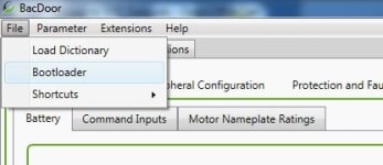
Then with the controller plugged in and connected, go to File->Bootloader and from there locate the Phaserunner_Default_Parameters_Fix.ehx file on your machine.
Bacdoor Bootloader.jpg
Hit Open and then it should fix the voltage and current calibration constants once you have power cycled the controller.

After that, you'll want to go to Parameter->Load From File, and then restore the original .xml parameter listing that you saved at the start of this process.

Let me know if that does the trick for you.
 
cavallo pazzo said:
Is there a reverse option on it ? Hidden wire, like on C7240-NC ?
Useful on trikes, heavy hauler and velomobile.Forgot to ask before placing the order.

Unfortunately this is NOT something that is supported. You can reverse the direction easily with software by setting the flag bit 0 from the "Motor Features" parameter.


But there is no facility at the moment to bring this out to a single wire input switch. It is on our future wish list for features but it would require a custom firmware from ASI to map one of the digital IOs to this functionality. In the meantime though, you can install a DPDT switch or relay on any pair of your motor phase wires and reverse the direction that way, which requires a switch/relay capable of handling the full phase current. But since you aren't switching live currents with voltage, there isn't any arcing or inrush current so the switch contacts should last quite long.

Alternately you could make a tiny micro circuit to communicate with the controller over modbus and set this bit to reverse as well. Might be a fun little embedded project if you're into that kind of thing.

If you'd want to cancel the order because of this then let me know. -Justin
 
justin_le said:
Next, download the enhanced xlm file from the site here:
http://www.ebikes.ca/downloads/Phaserunner_Default_Parameters_Fix.ehx

This looks encrypted... is that to keep people like me from setting the max amp setting higher than 74 or 80?? :mrgreen:
 
MrDude_1 said:
is that to keep people like me from setting the max amp setting higher than 74 or 80?? :mrgreen:

With the new parameter fix, it looks like the max phase current is 96A. A nice boost from the 74A of the BAC500.

Interestingly, the phase runner is giving me the same problem the bac500 did before it got a firmware update. There's a bit of stuttering under light load, which can sometimes result in over current faults. Under WOT it is usually fine. The motor still spins smoothly under no load, but will start hiccuping under light loads. The firmware update in January for the BAC500 fixed this completely and I never managed to replicate the issue even if I played around with the PI loop values. For now, I can reduce the current regulator gains which helps a little but by no means solves it.

Anybody have a similar issue?
 
district9prawn said:
MrDude_1 said:
is that to keep people like me from setting the max amp setting higher than 74 or 80?? :mrgreen:

With the new parameter fix, it looks like the max phase current is 96A. A nice boost from the 74A of the BAC500.

Interestingly, the phase runner is giving me the same problem the bac500 did before it got a firmware update. There's a bit of stuttering under light load, which can sometimes result in over current faults. Under WOT it is usually fine. The motor still spins smoothly under no load, but will start hiccuping under light loads. The firmware update in January for the BAC500 fixed this completely and I never managed to replicate the issue even if I played around with the PI loop values. For now, I can reduce the current regulator gains which helps a little but by no means solves it.

Anybody have a similar issue?
NICE. close enough to my old value of 100A that I wont mess with it... :lol:
I dont always need or use it, but its good to see it there for when I do.
 
Back
Top