Connecting Powered/Voltage Display Twist Throttle to Sabvoton Controller

But I do have a display and I do have PAS but the connectors and wires on the controller look exactly like the diagram I posted above. Here's pics of the display and the PAS number to the right changing.

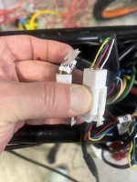
I do have a multimeter. So coming from the bundle i found a 3 wire "loop". Controller bundle has three wires yellow/green/black-going to a 3 pin connector, comes out yellow/green/brown and then back into controller bundle.
Can you point to where this loop connector appears on your diagram, and where the PAS and display wiring appear? How about the USB connector? If your diagram is EXACTLY like your controller, where are all the wires you are describing?

Check for 5v on the usb connector. The only time I bought a Sabvoton controller, I returned it due to a dead 5v source.
Also, according to the diagram i posted, you have to disconnect the 3 wire loop connector to enable the interface.

In fact, all the wires missing on your diagram appear on the one I posted including the 3wire loop that’s missing from yours so maybe look there as another reference..
 
One side question. Ive tried unsuccessfully to connect to this controller using MQCON on my iphone. I've tried several different BT adapters to plug into the USB port but for the life of me I can't figure out how to connect to it. None of the adapters I've used are showing up on the MQCON's BT MAC address list. Have you guys run into this or know why this might occur?
This poster has been in your place… no wiring diagram and no key switch solution. But he does seem to answer your Bluetooth question.


Edit: sorry E-HP hadn’t seen your post.

Still contemplating the key switch solution.

The diagram is much appreciated, well done!
 
The diagram is much appreciated, well done!
That Reddit post was helpful. It shows the two brake cutoffs are also part of the multi pin conductor. I think I saw this version of the controller relabeled by Rissun motor. Maybe it’s only meant for specific applications. I don’t see many sabvotons with HiGo connectors.
 
Can you point to where this loop connector appears on your diagram, and where the PAS and display wiring appear? How about the USB connector? If your diagram is EXACTLY like your controller, where are all the wires you are describing?

Check for 5v on the usb connector. The only time I bought a Sabvoton controller, I returned it due to a dead 5v source.
Also, according to the diagram i posted, you have to disconnect the 3 wire loop connector to enable the interface.

In fact, all the wires missing on your diagram appear on the one I posted including the 3wire loop that’s missing from yours so maybe look there as another reference..
Hi E-Hp, I hope you weren't talking my replies as anything other than what I meant and that is many thanks for helping out! I have yet to find a diagram that is completely the same as what the controller currently has. I only made those comments to say that parts of it are the same. That 3 wire loop is definitely not on any wiring diagram but its there so I drew it on the map I drew up yesterday and mentioned in my comments. There are probably 6-10 other wires connected directly to the controller or spliced in that were like that as well when I got the bike. This leads me to believe that when the alarm was installed that some of the wiring was changed and therefore would explain the reality of the wiring vs the diagrams of the wiring. I have reached out to the manufacturer who assembled this bike and they have been less than helpful and keep using the term debugging for everything which indicates to me that they are more clueless than I am.

I'm not sure if I'm just misreading your replies, but I was in no way complaining or arguing against anything you've said. I'm simply supplying what info I can provide. That said, at this point where do you think this blue wire coming from the throttle should be connected? Should it be spliced into the low voltage red cable going into the alarm? That's one of the only wires I found that had any power when the battery was on but the display was not.

Thoughts?
 
I forgot to mention, I did read (and saw it in a video) during some of my investigating the same comments in regards to disconnecting those wires for the display while trying to work on it. Otherwise the changes wouldn't take. I did try this and got an error message on the display so it does have some sort of impact. I'll have to go back and check what colors those wires are and it's possible that is the loop of 3 wires I reported. I thought I had tested that theory and still didnt' see the MAC address on the MQCON (sabvoton app) on my phone. I will say that there is a separate app for MQCON that helps you monitor BMS and I CAN see that MAC address and I do get interface and functional BMS stats but I've no idea what to do with them and I don't think they have anything to do with what we are trying to accomplish.

I'm happy to track down more wires, I just don't want to keep splicing randomly as the wires are getting pretty short so there's only so much room left for splices before the wires won't be long enough to do it anymore. So I have 2 suggestions if you guys are still willing to help me:

1. We can schedule a video call so I can test things real time
2. As you've done before, just give me a list of steps that I can try to follow but it seems like a slow process since i don't know what some of the terminology means (up to and including the i/f names you are using. My background is in network and firewall engineering so I'm been consoling into devices for 20 years so none of this scares me, I just don't know what it is I'm doing or what the expected outcomes of some of these changes are.

Ultimately, if you can write out what exactly this blue wire needs to connect into, I can also think about it and try to find that magical wire on the controller side.

Thanks again!
 
Can you point to where this loop connector appears on your diagram, and where the PAS and display wiring appear? How about the USB connector? If your diagram is EXACTLY like your controller, where are all the wires you are describing?

Check for 5v on the usb connector. The only time I bought a Sabvoton controller, I returned it due to a dead 5v source.
Also, according to the diagram i posted, you have to disconnect the 3 wire loop connector to enable the interface.

In fact, all the wires missing on your diagram appear on the one I posted including the 3wire loop that’s missing from yours so maybe look there as another reference..

I will update my diagram with the wires you asked about and repost it. I'll check the USB interface as well. I bought like 10 BT dongles in case it needed a specific version or whatever and one of them has LED indicator lights and it does power up when plugged in so its getting some power, I just don't know how much.
 
Just trying to separate the facts from the guesses so you don’t fry something. Statements like “cable that has like 8 pins in it” aren’t as helpful as counting the pins or posting a pic.
The diagram i posted appears to electrically match what you are describing, while the one you said matches has none of the wiring to support a display and PAS. The difference for the diagram i posted is that the conductors for PAS (+5v, gnd, PAS signal), low brake (+5v, gnd, brake signal), and display (+batt voltage, ignition signal, Tx, Rx, and gnd), are physically bundled into one cable harness, that splits into 4 connectors on the other end.
If you look at the pinouts for the UKC1 display, one of two compatible displays, it shows the same display connector pinout, with the same blue ignition wire. For your key switch, you want to insert the switch at the most convenient location, whether in the controller, or by opening the cable housing to snip the blue wire and insert the switch, wherever you feel is easiest to access.
 
The bottom of your second diagram is cutoff. The full version is below. If you are using the version of controller than supports a display and PAS, then the second diagram should be your controller, that shows the display connector at the bottom. The blue wire of the display connector is used by the display to turn the controller on or off. Inserting a switch in series with the blue wire would allow you interrupt that circuit so the controller can't be turned on by the display buttons, unless the key switch is turned on. Does the diagram below represent the version of controller that you have?:


View attachment 366032
Is this the diagram that you referring to that you believe is correct? If so, the reason why I haven't continued to use it is because the bottom connector (above the USB) is different than the one used in my setup. Secondly, I don't have a purple wire. Third, I believe I have 2 hall connections. One is connected from the controller in a bundle to a 6 port connector and goes to the battery in a 6 wire bundle, the other 6 port connector looks to be identical EXCEPT it has a white wire in the top middle port whereas the one in use does not have a wire coming from the controller in that slot. It does however have a white wire opposite the blank slot going to the battery. Not sure if there was a white wire there and it got pulled out or what (FWIW, I don't see any loose white wires but there is one connected to a 2 port male connector with a red wire but there is nothing on the other side (I've attached pics).

The loop I have is 3 wires and does match the diagram colors and is always looped. I tried disconnecting it and using MQCON and still not seeing a BT dongle adapter MAC address ( I tried 5 different dongles.)IMG_1165.PNGIMG_1158.JPGIMG_1159.JPGIMG_1160.JPGIMG_1161.JPGIMG_1162.JPGIMG_1166.JPGIMG_1163.PNG

I mention all of these things because it's hard to pick which diagram to use when NONE of them so far are exact matches so it's a combination of several of these so basically me drawing it out is the best way to document it. I was trying to avoid having to do all of this documentation if it wasn't needed to accomplish the task at hand. That said, I still don't know what color wire I'm looking for to splice the blue wire from the throttle into. Secondly does the yellow wire, stay as is and connected directly to the controller on red d+?
 
So everything runs right now as connected? Do you have a pic of the battery with the 6 wire bundle connected to it. The 6 pin with a white wire is usually a motor temp sensor wire, so if your motor doesn’t have a temp sensor, then it wouldn’t have a corresponding white wire on the motor side. Unless it’s a proprietary system, I wouldn’t expect anything but batt + and - going from the battery to controller.
 
No, well not really. The throttle works but it's not getting the correct output (ie wattage and speed) that Id expect out of a 5kw motor. I bought the bike used (it has less than 10 miles on it) and I basically stripped it down, replaced the brakes, the throttle, handlebar and some other stuff. I've been trying to connect to the controller so I can run the tests and any automated configurations since Sabvoton's are supposed to be easy, but this has proved to be anything but easy and I've spent a lot of time just doing administrative things to help explain what's going on with the bike even though I don't really know. Granted I have learned quite a bit just working on it. In any case, those 6 cables may not be going to the battery, they were headed that direction and since I'm really just trying to get the throttle working at this point, I didn't think it was imperative to trace them at this point and was trying to answer the slew of other questions first before moving on to new ones before answering a lot of the old ones . Wouldn't you agree to that methodology? I basically see 2 activities that I need to finish before moving on to tracing and drawing diagrams for literally every cable on this bike. Those are, 1. figure out where the blue wire from the throttle connects to on the bike? Does it possibly connect to the orange wire right before it goes into the alarm? And secondly, I need to figure out how to get connected to the controller via BT or the USB connection. Until I can do that, we will be troubleshooting in the dark and in reverse IMO. I've been trying to get some support from the company that built the bike and they seem to know less than me and just give me BS answers. Since none of these diagrams are exact representations and the seller has been no help then it's entirely possible that this controller is a one off design. It's even possible that the guy who "built" the bike bought a pallet full of these controllers for super cheap, because they had issues and Sabvoton didn't bother to support them, he then installed them and they worked-ish so he figured he could sell them and hope that no one notice the output He sold the bikes and now makes up any excuses to avoid having to ts the problems and saying its not under warranty. Sorry if I sound jaded and it sounds like that because I am. I have llterally purchased 7 e-bikes in less than 1 year, all of them new except this one, and every.single.one of them has had issues and I've spent hours, days and weeks trying to reverse engineer these damn things. Rant off. What do you think I need to do next to get the throttle working? Lets just focus on that until we get that resolved and not worry about anything else until then. Cool?
 
What do you think I need to do next to get the throttle working? Lets just focus on that until we get that resolved and not worry about anything else until then.
+1 (y)

Since Sabvoton's concept of "ignition" wire is different. You will most likely remove the YELLOW key switch wire from the battery+ terminal. And use it and the throttle's BLUE wire putting the key switch in series with the wire you're going to cut and splice into.
The YELLOW wire will go on the "HOT" side, and the BLUE will go on the "SWITCHED" side. (Energized only with the key switch on.)


Recommended requirements for the wire eventually being spliced into...

1) Supplies full battery+ voltage when battery on. (So digital voltage meter is taken advantage of.)
2) Draws less than 2 amps total with system on and running. (Typical throttle cable wiring maximum current capacity.)
3) Disables everything when disconnected during testing. (Dead as a doornail would be the best.)
4) In an easy and convenient place. :)

I agree not to cutting wires at random. After you find a wire that has full battery voltage with the battery on. And it has a connector in line with it. Perhaps remove that single wiring pin from the connector, disconnecting that wire to see if it disables the controller and hopefully the display also first. Or if advantageous, jumper all the other wires in connector, and leave the one being tested disconnected.

I like your suggestion of the ORANGE wire going to the alarm system. I'd look for connection as close to the controller as possible for testing. Or possibly any other ORANGE wire easy to get to and test..

I'm confused as to the statement that all alarm wires go directly to controller. Then show a connector which seem to fit the alarm wiring colors...? ORANGE, BLUE, and BROWN but going nowhere...?
Looked at your previous earlier pictures... perhaps directly, with connectors...?


Now I realize that E-HP is pressing to put the key switch in series with the BLUE wire going to the display. Unless I'm miss understanding that.
But this would seem difficult to get to. And if you do go to that trouble, and the last choice, wouldn't it be better to switch the #1 pin or RED wire supply voltage to the display? (With the key switch off, display could not be energized.)
 
No, well not really. The throttle works but it's not getting the correct output (ie wattage and speed) that Id expect out of a 5kw motor. I bought the bike used (it has less than 10 miles on it) and I basically stripped it down, replaced the brakes, the throttle, handlebar and some other stuff. I've been trying to connect to the controller so I can run the tests and any automated configurations since Sabvoton's are supposed to be easy, but this has proved to be anything but easy and I've spent a lot of time just doing administrative things to help explain what's going on with the bike even though I don't really know. Granted I have learned quite a bit just working on it. In any case, those 6 cables may not be going to the battery, they were headed that direction and since I'm really just trying to get the throttle working at this point, I didn't think it was imperative to trace them at this point and was trying to answer the slew of other questions first before moving on to new ones before answering a lot of the old ones . Wouldn't you agree to that methodology? I basically see 2 activities that I need to finish before moving on to tracing and drawing diagrams for literally every cable on this bike. Those are, 1. figure out where the blue wire from the throttle connects to on the bike? Does it possibly connect to the orange wire right before it goes into the alarm? And secondly, I need to figure out how to get connected to the controller via BT or the USB connection. Until I can do that, we will be troubleshooting in the dark and in reverse IMO. I've been trying to get some support from the company that built the bike and they seem to know less than me and just give me BS answers. Since none of these diagrams are exact representations and the seller has been no help then it's entirely possible that this controller is a one off design. It's even possible that the guy who "built" the bike bought a pallet full of these controllers for super cheap, because they had issues and Sabvoton didn't bother to support them, he then installed them and they worked-ish so he figured he could sell them and hope that no one notice the output He sold the bikes and now makes up any excuses to avoid having to ts the problems and saying its not under warranty. Sorry if I sound jaded and it sounds like that because I am. I have llterally purchased 7 e-bikes in less than 1 year, all of them new except this one, and every.single.one of them has had issues and I've spent hours, days and weeks trying to reverse engineer these damn things. Rant off. What do you think I need to do next to get the throttle working? Lets just focus on that until we get that resolved and not worry about anything else until then. Cool?
Did you buy the Bluetooth module from sabvoton? Looking at some listings for the Sabvoton version, some include a note that it isn’t compatible with other controllers, which may indicate its not a generic module, but some specific to Sabvoton.
The displays red conductor and blue are used to turn on the controller. Press the button, and the display sends battery voltage from the red wire to the blue wire to turn on the controller. You have a few options. One would be to switch the red wire. In that case, pressing the display on/off button will do nothing, and not energize the controller until you turn the key switch on. Switching the blue wire switch the blue wire would allow the display button to turn on the display, but won’t energize the controller. The thief will be confused when the bike doesn’t power up. You’d turn the switch on, then press the display button to power up the controller. To turn it off, you’d turn the switch off. Basically, when you press the display on/off, the display send battery voltage to the blue wire and the controller turns on.
A third option would be to use the key switch only to turn the controller on/off, which might be easiest for you. For that you’d cut the blue wire and pigtail the end coming from the display (not used) and connect the blue wire from the throttle to the end of the blue wire going to controller to turn the controller on/off independent of the display. This is similar to what TommyCat is suggesting. Now that I noticed that your throttle has what looks like a voltmeter, the key switch is also turning that on, so you can’t just insert it in series with the blue wire than if it was only used to turn on the controller.
You can open the controller to access the wires, or open the cable housing anywhere between the controller and display.
 
UGH. I typed out a lengthy reply and lost it all somehow. Well not doing that again so here is the nut shell and it only answers a few of the massive amount of questions.

1. The 5 wire bundle from the hall sensor does NOT go to the battery but instead goes to a thick wire that goes to the rear 5kw hub motor (supposed to be 5kw). Along with those 20-ih awg wires, there is also 3 other wires that come directly from the screw downs on the side of the controller, those 3 wires are green, blue and yellow (I've since updated the diagram.

2. The 5 singe wires from the alarm go directly to the large bundle coming out of the controller. This bundle is on the top left hand corner of the controller as depicted in the diagram.

3. Regarding the controller, I purchased the bike with around 10 miles on it as-is. The bike, for the most part, came from the manufacturer exactly as you see it. Especially when referring to the wiring. The only changes there are the replacement of the 5 wires for the new throttlel, voltage display and keylock. As it stands now, only the blue wire from the new throttle is not connected to anything.
 

Attachments

  • IMG_1191.jpg
    IMG_1191.jpg
    4.8 MB · Views: 3
E-HP, I don't mind cutting wiring, soldering, etc so we can do what is necessary but obviously I would prefer the easiest solution. That said, your last option of having the key turn everything on (controller, voltage display, regular display) is the way Id like to go. In that scenario, I would insert the key, exactly like a car, turn the key, and everything turns on. No need to individually push the power button on the display to get it working. I would assume in this scenario though that we would leave the button on top of the battery always depressed as it would need to be turned on and off everyime. Is there a downside to doing it this way? If not to all of those questions, how do I physically wire the connections? If provided this evening, I'll definitely do what is needed (provided the instructions are step by step and overkill if needed. Once I get all of this resolved, I will then move onto to attempting to figure out how to connect to the controller, so that I can troubleshoot the reason why I'm only seeing about 2800w from the motor. After that is done then I can go back and use another bag of zip ties to secure all of the wires back up. I do have one other wiring issue I need to investigate and I'm hoping that accessing the controller should make this task eaiser. As of right now, squezzing the brake levers does not light up a seoond set of back lights to indicate the brake is being used. I'm also not gettinng a flashing yellow light when the turn signals are activatd (in the rear) The yelllow light comes on but it doesn't flash. Manufacturer gave me some random excuse as to why he couldn't get it working but it was so absurd that it didn't register as being even somewhat logical to me so I skipped further ts'ing and decided to attack it later.
 
In that scenario, I would insert the key, exactly like a car, turn the key, and everything turns on. No need to individually push the power button on the display to get it working.


Not quite. The key would turn the controller on and off and the bike would run like a no display setup. But you’d need to turn on the display to use it or change assist levels, etc.
 
This is similar to what TommyCat is suggesting.

To be perfectly clear, my recommendation at this time would be to put the key switch in series between the battery+ and the display’s power input In the safest manner.

I.E. I wouldn’t leave a small single strand wire unprotected attached to the external battery post as it may be now…


After researching e-bike alarm wiring, I don’t think it would be a viable option.
Agreed, just isn’t as easy as using a display with JST connectors where the conductors are exposed. I did exactly what you’re describing in version 1 of my ebike. I tapped into the display JST near the controller, since the throttle wiring was there already. I used the switch to disable the ability to turn on the bike using the LCD3 buttons.
If you zoom in, you can see Im using the same throttle as the OP, or a half twist version.
econo-4-jpg.277297
 
Sorry for the delay, been sick the past few days. Ok, so I follow what you're saying about putting the switch (i.e. the blue wire) inline. Just so that I'm 100% understanding your solution (i.e. use the throttle switch/key to turn on the controller), would either of you mind drawing a little hand drawing or something that visually illustrates what you're suggesting? You can also use my diagram and draw over top of it if that makes it easier. I feel like you guys have put a lot of time and effort into helping me with this, so Id like to end this thread with a proven solution so if someone else comes along with the same issue (sans the sabvoton being annoying part, more on that later and probably a different thread) they can read through the entire thread and follow what we have done and not have to start a new thread or raise this one from the dead. Thanks again, guys and sorry for my terrible drawing skills, I need to get a license for Visio :ROFLMAO:
 
Agreed, just isn’t as easy as using a display with JST connectors where the conductors are exposed. I did exactly what you’re describing in version 1 of my ebike. I tapped into the display JST near the controller, since the throttle wiring was there already. I used the switch to disable the ability to turn on the bike using the LCD3 buttons.
If you zoom in, you can see Im using the same throttle as the OP, or a half twist version.
econo-4-jpg.277297

So I was thinking about your suggestions a little more and that basically we are trying to use the key switch (blue wire on throttle I think, please confirm?) to power on the controller. Initially I thought there might be a different wire between the controller and battery but apparently in it's current configuration that's not so since the controller doesn't turn on until I power on the display.

I'm not sure if this was taken in consideration but here's one more thing that might change the design. As it stands now, there is power button on the display, AND a power button on the battery case as well.

Lastly and finally some decent news. I finally got a Sabvoton branded BT adapter and cable, once I installed that into the SVMC7280 it finally showed up in the MQCON on my iphone. So now I'll have to do my research on how to reconfigure the controller if need to try and get the most out of the motor and controller.
 
Last edited:
To be perfectly clear, my recommendation at this time would be to put the key switch in series between the battery+ and the display’s power input In the safest manner.

I.E. I wouldn’t leave a small single strand wire unprotected attached to the external battery post as it may be now…


After researching e-bike alarm wiring, I don’t think it would be a viable option.
So it turns out, there is no good place to splice into the blue wire between the display and the controller. The wiring from the display all the way to the controller is bundled and connected using those round 3 pin connectors or 5 pins. . There aren't any JST connectors anyway along the way. So really I only see a few options, so correct me if I'm wrong.

1. Splice into those bundles (really don't want to do that)
2. Find a single wire coming out of the controller bundle and splice into that (wonder it would be another blue one).
3. Contact Sabvoton MQCON and see if they have a solution.
4. Upgrade to a fardriver controller. For those of you guys with fardriver experience, should i get a 72450 200a? I would prefer to get a higher amperage one that I can use for future projects as well. If not, which model?

Thanks!
 
Back
Top