Crystalyte Controllers - Repair and Modification information

The7 said:
Thanks for this piece of valuable information.
Grateful if you give an more detailed explanation and with an circuit diagram if possible.

there is a drawing of the 3525 pwm chip at the beginning of this thread. it is also used for low voltage cutoff and current limiting. values for the soft start cap and resulting timing are also discussed earlier in this thread.

if you mean a drawing of how to hook up the cycle analyst you will find that information on ebikes.ca

if you mean "a more detailed explanation" of how to defeat the speed/current limiting, you just disconnect the cycle analyst's output control line from the controller ebrake line (or throttle input) to prevent the cycle analyst from pulling down the throttle line. the CA will drive the control line low, and when nothing happens it will just keep trying. i believe there is a drawing of how the CA would be connected to the throttle line on ebikes.ca for cases where you cannot use the ebrake line or for controllers other than the crystalyte units, where the ebrake line may not be a linear signal as it is in the crystalytes.

for a similar implentation of current limiting pulling down the throttle line, see the thread on "fechter's current based throttle"
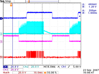
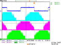
 
The7 said:
bobmcree said:
the reason i thought this belonged in this thread is a discussion of how the limiting is achieved. the KA3525 pwm chip in these controllers is used in a somewhat non-standard configuration. the regular pwm input of the chip is not used at all. all control is done via the soft-start capacitor input. this thread has previously discussed how changing the value of this cap can change the "attack" time of the throttle.

Thanks for this piece of valuable information.
Grateful if you give an more detailed explanation and with an circuit diagram if possible.

I am referring to "all control is done via the soft-start capacitor input" because it seems that the throttle control is also done via the soft-start capacitor input.

If so, how is the throttle control achieved via this soft-start cap input?
 
The7 said:
The7 said:
bobmcree said:


I am referring to "all control is done via the soft-start capacitor input" because it seems that the throttle control is also done via the soft-start capacitor input.

If so, how is the throttle control achieved via this soft-start cap input?

sorry, i just wanted to be sure what you were asking. the KA3525A chip is used to create the pwm signal that is anded with the high side drive for variable throttle control. when i was trying to figure out the circuit they use on the controller by looking at the 3525 data sheet it became obvious that they do not use the normal input provided for the throttle signal. the soft-start circuit in the chip ramps up the duty cycle when the throttle signal is fully asserted, and in this controller instead of driving the separate analog input they just override the ramp voltage on the soft-start cap to achieve control.

in the attached data sheet there is a test diagram that shows the duty cycle controlled by a pot on the error amp input, and a cap connected to soft start. in these controllers they drive the soft start cap line with the throttle signal, and they use the input comparator for the current limiting.

they also do something funny using the power pin as the output if i recall the drawing i still have buried in my moving boxes.

as long as the current limiting is not active and the undervoltage lockout is not asserted, the duty cycle follows the voltage on the soft start cap. the charge current is limited internally so if you hit full throttle with a current limited source the soft start cap value controls the ramp rate. the cycle analyst and fechter's current limiting throttle use a diode in series with their output signal tied into the throttle signal, so that they can only pull the voltage down, not drive it up. this turns out to be a very good way to control speed and current but it can oscillate or jump around the setpoint without some software filtering and loop constants that can be modified in the advanced setup menu of the cycle analyst.
 

Attachments

  • ka3525a.pdf
    84.1 KB · Views: 210
bobmcree said:
a simple switch connecting the limiter signal to the ebrake signal can be mounted where it is easily accessable, permitting instant enable/disable of the limiting functions.

I believe that switch goes by the vernacular 'econo/turbo switch' as found on most turnkey systems or multi-level settings as on the BionX.
Their implementation may or may not be different, but the end result's the same.
 
bobmcree said:

Thanks for this valuable piece of your finding.
It has been bugging me since I read about KA3525A in fechter’s post.
Now it does give me a clear picture “how is the throttle control achieved via this soft-start cap input X-controller”.
Thanks again. Bobmcree.

Further studying from fechter’s post on current limit and LVC ; from bobmcree’s explanation and from KA3525A data on X-controller:
X-cont uses 10uF as soft-start cap.
Soft-start current =51 uA
Time to ramp to 0.5V = (10u * 0.5) /51u = 0.1 sec (LAG time for the throttle).
Time to ramp to (0.5V to 4.0V) = (10u * 3.5) /51u = 0.7 sec (Ramp-up time for the throttle)

The ramp-up time should be acceptable because no ebike could reach its top-speed within 0.7 sec.
I find that the LAG time of 0.1 sec (worst case could be 0.2 sec) is annoying because the ebike does not response to my throttling immediately. I did ride motorcycle in my young age and did not notice such a LAG time.

To minimise this LAG time.
1) Fechter has suggested an way by adding an tim-pot at one end of the throttle negative :” Here's an easy mod that improves the low speed throttle response.”
http://endless-sphere.com/forums/viewtopic.php?t=764&postdays=0&postorder=asc&start=45
2) Change 10uF to 2.2uF as done by Doctorbass. LAG time becomes 0.02 sec and ramp-up time 0.16 sec. This is easily done on 12 FET controller, but it is a bit difficult on 6 FET controller.
3)XXX My susgestion: Connect a diode between the output of the Hall-effect throttle and the throttle input of the X-controller. The bar (cathode) of the diode is at the Hall throttle side. The forward drop of the diode should be about 0.4V-0.7V ( try 1N4148). This diode will maintain an voltage of about 0.5V on the 10uF when the throttle is OFF. Then the LAG time could be negligible.XXX
Correction for (3) after implement in my 20A X-controller (2007/08/27 11:00pm). An diode 1N4007 is connected between the 0V of the Hall-effect throttle and the 0V of the throttle input of the controller. The bar (cathode) of the diode is at the 0V of the controller input. The idle voltage of throttle input is raised from 0.834V to 1.464V. The Lag tme is decreased to an acceptable value.

4) You could use (2) and (3) together if you like.
 
Doctorbass said:
The7,

when you did your test with no lead and measured the current, are you sure that your ammeter is enough quick to get the high current peak?

I had this problem when I tested with my DC clamp meter and the cycleanalyst. the cycle analyst seems to be much more faster than the Clamp meter!... The meter have a latch and the display is about 0.5s latch..

I will try to measure it using my 50A shunt + a scope :wink: I will post the pic of the phosphore screen...

Doc

Doc,
Still waiting for the pic!
 
i have done a bit more reverse engineering of the throttle circuit, and am working on a schematic, but here are a few points relevant to the current discussion:

1) the throttle input is processed by an op amp which subtracts a volt of offset and then scales 1-4v to 0-5v which is buffered and then fed directly to the soft-start cap + to over-ride the 3525 internal circuit.

2) the op amp in the 3525 is used for current limiting instead of the intended use as an error amp in a servo loop which would permit a true current feedback for the throttle. it may be possible with some hacking to implement a closed loop throttle with true current feedback

3) there is a circuit that uses the 15v gate pulses to the low side fets on the blue channel to keep a cap charged that discharges when the motor is not turning to assert the shutdown pin 10 of the 3525, clamping the soft start cap and keeping the pwm at 0. you can see this function if you look at the voltage on the soft start cap as you adjust the throttle without a motor attached; the voltage will first rise, then be clamped down to 0 when there is no switching transition due to no change in hall sensor status. this provides some protection in a stall condition, but it is not by any means complete protection in a stall/full throttle event.

4) the ebrake just pulls down the throttle input through a diode and current limiting is provided. this input can also be used for power limiting by the cycle analyst or other regulating hardware
 
Thanks Bob,
I never got around to fully reverse engineering that part of the circuit. Some of the traces appear to run under the op amps, and I didn't want to remove them off a perfectly good controller just to see where they ran.

I did notice the PWM gets killed after about a second if there are no changes in the hall signals. It might protect against the motor windings getting fried in a stall condition. Assuming the FETs don't blow first.

It would be cool to implement a true current servo loop. In the present setup, the voltage range on the input to the error amp is very small, and of course, one side of it is used for the LVC. It might require adding or rewiring another op amp to scale the input.

The other 'gray' area for me is the LVC circuit. The two controllers I've looked at closely did not have the same resistor values, and on one of them the markings on the resistor don't seem to match their actual resistance. I guess it would be nice to come up with a table of resistance values for various LVC voltages. This way people could customize their LVC without too much guesswork.
 
The low voltage cutoff resistor chart would be great. Does nobody already know the figures? I remember when I first an x'lyte controller everyone said you could do it, but noone ever forwarded and real data...
 
fechter said:
I did notice the PWM gets killed after about a second if there are no changes in the hall signals. It might protect against the motor windings getting fried in a stall condition. Assuming the FETs don't blow first.
Crystyalyte 20A 36-72 volt controller,
If I prop my hub motor wheel off the ground, shut off the power first. Then I duct tape the throttle wide open and flip the power back on, the wheel doesn't spin, no weird noises or jerks. But as soon as I spin the wheel, it come to life at full speed. Would that behavior be a good example of this?
 
knightmb said:
fechter said:
I did notice the PWM gets killed after about a second if there are no changes in the hall signals. It might protect against the motor windings getting fried in a stall condition. Assuming the FETs don't blow first.
Crystyalyte 20A 36-72 volt controller,
If I prop my hub motor wheel off the ground, shut off the power first. Then I duct tape the throttle wide open and flip the power back on, the wheel doesn't spin, no weird noises or jerks. But as soon as I spin the wheel, it come to life at full speed. Would that behavior be a good example of this?

tim, that sounds more like the behavior i would expect from a system that was not switching properly, but i would never power up with the throttle full on myself. the only time i have seen that behavior was when the low side fet on a single channel was not working, and when that channel was the one that was selected to start the motor by the hall sensors. it would be revealing to see if the behavior changes with slightly different starting rotational position. the shutdown signal is clamped internally by 2 diode drops, so it is asserted above 1.6v or so. if the system is not starting and the shutdown is not asserted, it might be the case that starting power up with the soft start cap fully charged triggers the current limiter or that the failure of an edge on the fet gate fails to trigger the watchdog circuit and it does not de-assert the shutdown.

the throttle signal simply charges up the soft start cap, and the gate pulses of the right hand channel charge up the cap that keeps the op amp circuit from asserting the shutdown signal on pin 10 of the 3525. it may be that there is a startup condition when full throttle is asserted that causes the current limiter or low voltage cutoff to be asserted.

actually after a bit more thought i believe i have the answer; the cap that needs to be charged up to de-assert the shutdown signal is charged up the first time by the change in voltage of the throttle signal, so if the throttle signal is static i suspect the shutdown signal is held on until the hall sensor causes the gate of the fet to be switched, charging up the cap in the watchdog circuit.

you could tell by looking at the voltage on pin 10 of the 3525
 
fechter said:
If the gate resistors blew, there's a 50% or so chance that the gate driver chip or the two transistors on the high side drive also blew. These are difficult to test without connecting a motor.

In the absence of hall signals, the controller will not produce any output, so the only way to test is to connect a motor. If you want to probe the gate signals, you will have to power up the controller with the cover off and have the motor connected. This is a PITA. I found a tiny brushless motor that I use for bench testing, but the full sized motor will work.

Any faults in the hall signals or gate drives might result in shorts to the battery, so testing should be done with a current limited power supply. If you don't have a bench supply, use a small fuse (5 amp?) or something like a car headlight bulb in series with the battery to prevent overcurrent.

I replaced a blown gate driver chip by using solder wick and a razor blade to remove the old chip. Soldering tiny smd chips is challenging. I wrap a small piece of solid copper wire around the tip of my soldering iron to make a 'stinger' small enough to heat one leg at a time. After flowing the solder, drag the tip away from the chip, parallel to the legs to prevent bridging adjacent legs. If you bridge them badly, you'll need to use solderwick again to clean them.

Sorry if I missed it, I had a good look through the thread, exactly how do you test the gate drivers? probes where? And what result to expect?

Thanks Boss :wink:
jozz
 
the diagram for the ir2101 driver shows the input and output pins. if you look at the board with the connector for the hall sensors down and left, from right to left the signals on the 5 pin connector are are +,-.s1,s2,s3

s1 drives the left channel, s2 center, s3 right. this drives the low side output which is on when a phase is selected. the high side is driven with the pwm which is difficult to trouble shoot without a motor attached. there is a bootstrap cap on each 2101 that produces a higher voltage for gate drive of the high side, and a transistor drive circuit boosts current to the high side fets; there is a schematic of that circuit in the schematics thread.

the gate resistors are 10 ohms and can be easily tested with an ohmmeter. they mostly function as fuses so when the gate shorts the driver chip is protected. this usually works to protect the 2101's.

if you measure between the gates of each pair of fets you will see 20 ohms and from the 2101 to each fet gate is 10 ohms. it is generally a good idea to replace the resistors if the fets are blown even if they seem ok, as they have probably been stressed way beyond normal operating limits.

it is best to troubleshoot the controller with a current limited power supply to avoid damaging it further if there are problems. a couple of amps is enough to run it with no load on a typical motor, and will let you watch things change as the motor turns.
 
Thanks Bob. I am repairing a 20A controller, so the orientation is probably different, but now I know what to test for I can easily find my way by comparing that driver to the other 2 in the unaffected circuits. The gate resistor on the affected phase was blown, along with the cap and diode, and another tiny resistor attached to the first leg of the fet (a "5r1". If anyone needs any, I now have 4999 left! Damn high minimum order!)
If the ir2101 driver is blown, do I risk the whole circuit again if I just try it on the motor with current limiter set to minimum and a fuse of just a few amps? (got no current limited supply yet, next on list of things to buy)

How was the fishing?
 
sorry for any confusion, obviously in the 20a units there is not a pair of gate resistors since there is just a single high side and low side fet for each of the 3 channels.

if you have not done so you should check the fets with a meter to look for shorts. after checking them if you connect power through a 1A fuse with the motor phases disconnected but hall sensors connected you can look at the inputs and outputs of the 2101 and you can turn on the low side output by turning the motor to trigger the appropriate channel. you can also look at the high side output and should be able to tell if it is shorted or open.

another trick i think fechter mentioned is using a light bulb in series with the power to limit the current when you can't use a limiting supply. i have also used a 4 to 10 ohm power resistor which will limit current to a few amps.

fishing was pretty good, catching not quite as good. i caught several that were not in the legal size range to keep, but my friend did a bit better, so we got to eat....
 
So after blowing out my 72V 35A controller I tried to fix it.

First I replaced the FETs. No good. One phase is still 'stuck.'

So I took it apart again, instrumented it and tried a few things. Removing all the FETs from the bad phase resulted in a motor that would sorta spin (with some help starting) and I was able to capture some plots. (Three phase motors can often be made to spin with one phase not working, as long as you help it start.)

I looked at all the signals going to the "bad" FETs and found one bad gate resistor. Replaced that, added yet more FETs, and tried it again. Still nothing! I tried spinning the motor by hand, and it started up. Experimented with it a while and it works fine once moving - but won't start from a stop.

So it looks like I've created a "pedal first" controller from an "instant start" controller. Wonder how I did that?

Before I reassemble it I want to get some shoulder washers so I don't have to deal with these cheezy shrink-tube-insulated screws. With my luck it will wear through and blow out again.

Edited to add- by the way, my controller had no FET drivers, just a triple 3-input AND gate that did the throttle signal gating and drove the FETs directly. Odd.
 

Attachments

  • hall_sensor_outputs[blu_grn_yel].png
    hall_sensor_outputs[blu_grn_yel].png
    6.8 KB · Views: 3,635
  • hallsensor_phase_lowgatedrive_highgatedrive.png
    hallsensor_phase_lowgatedrive_highgatedrive.png
    9.7 KB · Views: 3,639
  • three_phases.png
    three_phases.png
    14.4 KB · Views: 3,639
Cool scope displays.

Is that a Crystalyte controller?

Does it have a C1246 commutator?

If one phase is not working, the motor will not start on its own from some positions. It may start from other positions. You can attempt repositioning the wheel many times and see if it will start.

In your case, the signals appear to look OK, so I'm not sure why it wouldn't start on its own.

If you look at the high side gates, you'll typically see one of them get the PWM signal when you apply the throttle. The PWM usually drops out after a couple of seconds if the hall inputs don't change. This is a locked-rotor protection of some sort.

If you spin the motor backward with the controller on (no throttle), you should feel a steady resistance. If one phase is out, you will feel a pronounced cogging.

With the motor attached, the BEMF from the motor might give a signal even where one of the phases isn't firing. You could disconnect the phase wires from the motor, but keep the halls connected. Give some throttle, spin the wheel, and scope the phase wires from the controller to make sure they're all switching properly.
 
>Is that a Crystalyte controller?

Label - "Crystalyte 36-72V 35A immediate start"

>Does it have a C1246 commutator?

Yes, and the 3525. But no FET drivers. Odd.

>In your case, the signals appear to look OK, so I'm not sure why it
>wouldn't start on its own.

After further experimenting, I discovered that it wants to see a zero throttle signal before starting. I'm using an adjustable pot, and when it's set to about midrange it won't start until I back it off and ramp it back up.
 
billvon said:
>Is that a Crystalyte controller?

Label - "Crystalyte 36-72V 35A immediate start"

>Does it have a C1246 commutator?

Yes, and the 3525. But no FET drivers. Odd.

>In your case, the signals appear to look OK, so I'm not sure why it
>wouldn't start on its own.

After further experimenting, I discovered that it wants to see a zero throttle signal before starting. I'm using an adjustable pot, and when it's set to about midrange it won't start until I back it off and ramp it back up.

i have never seen a crystalyte controller with no ir2101 drivers, but i heard they were coming out with a new design, and you never know what pcb the chinese will stick into the same box. from your symptoms, i would suspect what i call the "watchdog" circuit, which keeps the pwm from working if there is no switching on one of the output channels.

look at pin 10 of the 3525, and if it is being driven above 1.6v that will shut down the 3525. this is done with an op amp driven by the right hand channel on the controllers i have seen. when you first power up the signal should be high, and it should go low when you move the throttle. if it dies right away there may be a problem with this circuit.

can you post a picture of the controller pcb?
 
bobmcree said:
can you post a picture of the controller pcb?

Sure, although there are so many extra wires going to this thing it's hard to see:
 

Attachments

  • board_top.jpg
    board_top.jpg
    103.5 KB · Views: 1,250
  • board_bottom.jpg
    board_bottom.jpg
    109.7 KB · Views: 1,234
The 2101's are hiding under the capacitors. See pic.
 

Attachments

  • 2101's hiding.jpg
    2101's hiding.jpg
    49.3 KB · Views: 3,589
billvon said:
After further experimenting, I discovered that it wants to see a zero throttle signal before starting. I'm using an adjustable pot, and when it's set to about midrange it won't start until I back it off and ramp it back up.

Seems that this is an safety feature of the controller.
I did a test on an old Xlye 20A version. If I lock the drive wheel too hard and give an throttle, the drive wheel tries to turn but not able due to hard braking. An large current (at 20A limit) will flow a second or so and the controller protection takes over and cuts off the supply. If I still hold the throttle ON, the protection cut-off remains. It will only reset if the throttle is returned to its idle (OFF) position.
I think that the protection of your 35A controller would behave in a similar way.
 
Does anyone know if the new Crystalyte controller, shown below, can have the same sort of FET upgrade?

New-4840.jpg


There aren't any 72V versions of this new design yet, that I know of.

-- Gary
 
GGoodrum said:
Does anyone know if the new Crystalyte controller, shown below, can have the same sort of FET upgrade?

New-4840.jpg


There aren't any 72V versions of this new design yet, that I know of.

-- Gary

I'm sure it could. We'll see how the stock FETs hold up, they might be OK.
Justin seems to have a ton of information on these new ones, so we should be able to figure it out.
 
Back
Top