parabellum
1 MW
Nieles, what hall sensors will be used or better what current range can be used on this test batch?
parabellum said:Nieles, what hall sensors will be used or better what current range can be used on this test batch?
rhitee05 said:Here's the feature set for the prototype:
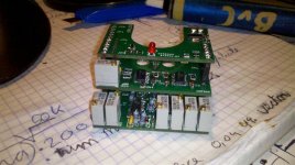
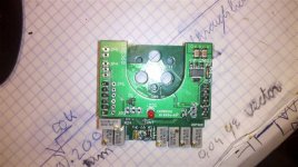
- Custom hall-based 3-phase current sensor. The sensor should have fully-linear range of >300A, >200A, or >150A depending on the sensitivity of the sensors used. Sensor is fully isolated and insulated from the phase wires - the current design just has 3 0.25" dia holes which the phase wires pass through. I have some 8 ga wire which passes through easily.
- Interfaces to standard 5V e-bike throttle, hall- or pot-based. 5V supply is provided to the throttle. Currently both gain and offset adjustments are included.
- Option for either pass-thru throttle or closed-loop current-based throttle (selectable by jumper).
- Throttle filtering with separate up/down ramp times if desired (ramp-down time <= ramp-up time). Filtering can be disabled by removal of a capacitor.
- Option for throttle "boost" which provides temporary 10-30% (set by fixed resistor) increase in throttle gain. Boost is activated by a momentary pushbutton.
- Phase current limiting via 2 separate limits (works for either direct or closed-loop throttle). One limit has a fast, aggressive response, the second has a slower, integrating response which is less aggressive.
- Includes servo interface directly to ESC with adjustable min/max pulsewidths. Pulse rate is set via a fixed resistor (50 Hz nominal). Prototype is designed to drive ESCs only, but future versions will have a 0-5V output to drive a standard controller instead.
- Current design generates 5V supply directly from the battery. Future versions will probably make that optional, either internal 5V supply or taken from an external BEC, and will probably use a switching regulator rather than the current linear regulator.
Thud said:Eric,
Thanks for the continued support on this little project. I have pmed Nieles & am waiting to hear what his schedual is....
I have a new fightercat sensorless controller here good for 16cells ready for some serious testing.
if this limiter works as planned it will be a huge boone to the rc crowd....or the sensorless crowd in general. I know a CChv160 is not a cheap controller....but in side by side testing....it will destroy a 12fet xiechang controller in acceleration & performance.
I assume the current limiter will take some of the edge off the lil' neck breaker, but i have high hopes.
Thanks Eric & alpha-beta testers for continuing to provide some support here with documentation & ideas & dev. I wish I had the ability to help out but can only standby for testing after initial prototypes prove to work.rhitee05 said:I'll also point out, regarding the BOM, that not all of the parts on the board are intended to be populated. There are several places where I put components on the layout for "just in case" and several places where the intention was to place either component A or component B, but not both. All that will be explained in the documentation.
I'm glad you like the layout. I just hope you aren't cursing me under your breath while you're soldering SMT components... You might've also noticed that there's a mixture of SMT and thru-hole components. I was trying to be nice to future users, so that I used thru-hole for components I anticipate might need to be changed to enable a feature or to tweak a parameter.
crossbreak said:Please keep on developing! I'm a poor student, but five or 10 bucks would be ok for me (I already translatet patents for less) if you write a documentation and upload an image pcb.
Next year I could make use of it when my next bike is ready. It has a T-80-100 KV130 and ATM I'm testing my config with a 6-FET stock controller which did at least can't blow
I don't ever want to blow a controller in my live (don't bet on me)
nieles said:i will see if i can get some flux rings lasercut for future units.
eric, will it matter that the material for the flux rings is 3mm instead of 1/8 inch (3.175mm)?


