Cycle Analyst V3 preview and first beta release

izeman said:
...the bms totally CUTS the power to the controller, shutting everything down.

thx, I'll study the details...

the new FoundingPower CS-BMS (and EBS-BMS) only cut off the charging current and the auxiliary supply current (lights, CA, ...) - the main discharge current via the controller is cut off via a throttle limiter signal (pull down throttle signal either 'binary' or 'continously' with a PWM signal...)
 
rolf_w said:
the new FoundingPower CS-BMS (and EBS-BMS) only cut off the charging current and the auxiliary supply current (lights, CA, ...) - the main discharge current via the controller is cut off via a throttle limiter signal (pull down throttle signal either 'binary' or 'continously' with a PWM signal...)
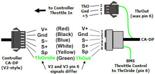
This BMS seems to use the same interface as the legacy CA V2 'limiting' interface that is unused with the V3. So we just hook it up like the V2 using the existing controller connector. The BMS and V3 will live happily together.

  • If you examine method 1 of throttle hookup for the V3 in Appendix B of the Guide, you will see that the V3 ThrottleOut connection (green wire - pin 6) of the CA-DP connector is disconnected and is re-directed to the actual controller throttle input (pin 3).
  • Connect the BMS limiting output to the CA-DP pin 6 where it will drive the controller ThrOverride input (CA-V2-compatible).
Important: be sure your controller has a V2 NOT V3 CA-DP connector. This can be made to work with a V3 compatible controller, but it may take an extra diode and resistor to implement the throttle override. Still easily doable, though...

CADP-V3-BMSV3.png
 
Not sure if this is the place to post but I had an incident today while the CAV3 was in "Auto Cruise" . I was heading downhill with the "Auto Cruise" on and forgot that it was engaged because I was also peddling. I then came to a quick stop to check something on the bike and jump off and forgetting the cruise was still engaged I let go the brake and off she went!!! Luckily I only busted my rear safety light. I know this is my fault but it would be a nice feature if the "Auto Cruise" would automatically turn off if your speed is zero.
 
oldtown169 said:
... I let go the brake and off she went!!! ... I know this is my fault but it would be a nice feature if the "Auto Cruise" would automatically turn off if your speed is zero.
This is a little confusing - auto-cruise disengages when ebrakes are applied.

Do you have ebrakes, or if not, did you just overpower the motor with the handbrakes to stop the bike?
 
teklektik said:
oldtown169 said:
... I let go the brake and off she went!!! ... I know this is my fault but it would be a nice feature if the "Auto Cruise" would automatically turn off if your speed is zero.
This is a little confusing - auto-cruise disengages when ebrakes are applied.

Do you have ebrakes, or if not, did you just overpower the motor with the handbrakes to stop the bike?

The way mine works is : My ebrakes cut the power to the motor but when I let go of the ebrakes the cruise (power) cuts back on. So when I stopped I had the brakes engaged but as soon as I got off the bike I let go of the brakes and off she went.
 
oldtown169 said:
My ebrakes cut the power to the motor but when I let go of the ebrakes the cruise (power) cuts back on.
This is not working correctly at all.
Which firmware version are you using?
Are your ebrakes attached to the V3 or the controller?
 
oldtown169 said:
When I turn on the CA it says Ver3 Prlm5 is this the firmware?
Yes. It won't affect this problem, but you should move up to P6 at your earliest opportunity to get to the contemporary supported version.

oldtown169 said:
Ebrakes are connected to the controller.
You need to connect your ebrakes to the V3 instead.
Using V3 auto-cruise without the ebrake input is very dangerous as you discovered.

In your present configuration, the CA cannot tell that the ebrakes have been applied and so the auto-cruise remains engaged. If you examine the Throttle OUT field on the diagnostic screen with auto-cruise engaged, you will see that the throttle voltage to the controller is unchanged when you apply the brakes. The ebrakes are instead cutting the controller power downstream, so when they are released the auto-cruise throttle setting immediately takes effect.

By attaching the ebrakes to the CA, applying them will cause the Throttle OUT voltage will go to the ThrO->BrakeOut voltage (typically 0v) to stop the motor and (importantly) cruise will disengage.

Hmmm - guess this deserves a caveat in the Guide......
 
teklektik said:
oldtown169 said:
When I turn on the CA it says Ver3 Prlm5 is this the firmware?
Yes. It won't affect this problem, but you should move up to P6 at your earliest opportunity to get to the contemporary supported version.

oldtown169 said:
Ebrakes are connected to the controller.
You need to connect your ebrakes to the V3 instead.
Using V3 auto-cruise without the ebrake input is very dangerous as you discovered.

In your present configuration, the CA cannot tell that the ebrakes have been applied and so the auto-cruise remains engaged. If you examine the Throttle OUT field on the diagnostic screen with auto-cruise engaged, you will see that the throttle voltage to the controller is unchanged when you apply the brakes. The ebrakes are instead cutting the controller power downstream, so when they are released the auto-cruise throttle setting immediately takes effect.

By attaching the ebrakes to the CA, applying them will cause the Throttle OUT voltage will go to the ThrO->BrakeOut voltage (typically 0v) to stop the motor and (importantly) cruise will disengage.

Hmmm - guess this deserves a caveat in the Guide......

I had to do this with one of cellman's Infineon / MAC kits and the CAv3. It's fairly trivial to do but you gotta get some JST-SM connectors and such.
I did it because I like the brake animation :) Also having short and sweet cables at the front is better than having two more cables run the length of the bike to the controller.
 
Hi all,
Just wanted to give my feedback on Prelim6.

Very happy that the datalogging output is working for all settings.
Ramping units in V/Sec works well for me. Ramp down is at 99.99V/Sec (immediately). Running everything in Power throttle. Wgain is at 5. However, if after strong acceleration (>50A) I abruptly let go of the throttle, I can feel a power surge for a milisecond before all power dies. I will try out different Wgain settings.

Previously, I had set the threshold higher, which meant that I ran into abrupt power decreases when the motor got too hot, which is inconvenient. Now my Temp threshold is set at 70oC with cutoff at 130oC. Despite very warm weather (up to 30oC ambient) and long hilly rides with hills up to 40% grade, the motor never got warmer than 120oC. The very gradual decrease in power induced by the low threshold makes for very easy driving.

I use 20S Lipo (84V HOC, 74V Nominal) with a CA LVC at 60V. I know that this is way too low for my Lipos, but we are not talking about resting voltage. If resting voltage is 70V it is time for me to cut the power. That means that I can still have some power to limp home with incredible voltage sagging under small loads. I have done this now twice, and I have the feeling that the battery gauge on the CA correctly reflect my feelings of (dis)comfort while emptying my Lipos...
PAS settings not tried yet.

[youtube]Ss4rk2PdQVI[/youtube]

Also posted in a separate thread here.
 
teklektik said:
oldtown169 said:
When I turn on the CA it says Ver3 Prlm5 is this the firmware?
Yes. It won't affect this problem, but you should move up to P6 at your earliest opportunity to get to the contemporary supported version.

oldtown169 said:
Ebrakes are connected to the controller.
You need to connect your ebrakes to the V3 instead.
Using V3 auto-cruise without the ebrake input is very dangerous as you discovered.

In your present configuration, the CA cannot tell that the ebrakes have been applied and so the auto-cruise remains engaged. If you examine the Throttle OUT field on the diagnostic screen with auto-cruise engaged, you will see that the throttle voltage to the controller is unchanged when you apply the brakes. The ebrakes are instead cutting the controller power downstream, so when they are released the auto-cruise throttle setting immediately takes effect.

By attaching the ebrakes to the CA, applying them will cause the Throttle OUT voltage will go to the ThrO->BrakeOut voltage (typically 0v) to stop the motor and (importantly) cruise will disengage.

Hmmm - guess this deserves a caveat in the Guide......
Thanks teklektik. I guess I'll have to change the connector so it will fit into the CA's plug? Where would I find a source for the connector and instructions to change/crimp it? I did receive my kit from EM3EV....
 
oldtown169 said:
I guess I'll have to change the connector so it will fit into the CA's plug? Where would I find a source for the connector and instructions to change/crimp it? I did receive my kit from EM3EV....
Yep - that looks like the solution....

Connector pinouts are in the Guide.

Crimping instructions here, but this is using a fairly expensive crimper if you are just looking at one-time use. You can make do with Molex, etc crimpers if you have one - or even small needle nose pliers if you are very careful and solder it afterward (the fit in the plastic shroud is pretty close for the crimped region of the pin - crimper is recommended).

The connectors and pins are incredibly uneconomical to buy in small quantities - largely because of shipping. Maybe someone can step up with a good source. Ebike vendors sometimes sell a mixed bag of common sizes for cheap that are always a good 'filler' item to add onto an order so there's no shipping cost. ebikes.ca has such an item (CONBAG) but the shipping is killer. You might email them and see if they might just post you the tiny bag in an envelope instead.

If you don't do this crimping thing a lot, you might also buy a 4-pin JST-SM with a tail attached and just splice it on and seal with shrink. Searching eBay shows quite a few of these. A quick Google search gets some RC suppliers with prices under $2 US. Your local RC hobby shop might have the connector w/tail as well (bring a picture ;)).
 
An updated version of the Unofficial Used Guide is available here. This should bring things up to date with 3.0Prelim6.

Updates are mostly small alterations to accommodate the changes in ramping parameter naming and units. Also added some caveats to address the conflicts between CA/controller ebrake and auto-cruise operation that have come up in recent posts (as always: Thanks for the posts!). There hasn't been any feedback on the latest AutoTorqPAS hack, so I didn't include it this time around - it's still a separate doc, but relocated to the UUG download page.

Enjoy!
 
Printable Setup Summary for CA v3.0 Prelim6

The setting summary for the previous CA v3.0 Prelim5 release is available here.
Unofficial User Guide is available here.
Please see the Grin Tech Site for a detailed explanation of Setup Parameters.

Distinguishes global from preset-specific parameters.
Editable and printable versions for saving settings - tabular format for multiple presets - formats: 1UP.PDF, 2UP.PDF, FORM.XLS

View attachment CA_V3-0Prelim6_ConfigSettings_c.zip
 
teklektik said:
Luge_a_foin said:
p.s. and I've sent a mail to the source.
Thanks for the updates - that clarified the electrical situation. Hopefully this information will jump start Justin's efforts to solve this. Please post back when you get this resolved - this may be stuff for the Guide... :)

Hi,
Finally thanks to Justin I have solved my problem. A resistor was damaged (probably with a transient short between V+ & ThO). So I have resoldered another one and it works now perfectly.
Many thanks to Justin & teklektik for their kind help.

I've got another question. I don't know if it is related to CA but I have great variation (80-100W) of the steady bike consumption during the day. For example I can zero it the morning and have -80W the afternoon (I use my bike to go to work). Has anyone an explanation to this behavior? I haven't noticed it before, at least in such a huge amount.
 
When I have had that problem it was caused by a poor connection at the CA connector for the shunt wires. Sometimes it's oxidation and sometimes just bent or worn/poorly-fitting pins. (one reason I dislike the JST connectors because they do that a lot, at least to me, even if they're never connection-cycled).
 
amberwolf said:
When I have had that problem it was caused by a poor connection at the CA connector for the shunt wires. Sometimes it's oxidation and sometimes just bent or worn/poorly-fitting pins. (one reason I dislike the JST connectors because they do that a lot, at least to me, even if they're never connection-cycled).

I think you're right as I've noticed some oxydation on the V+. What do you use for CA connectors instead of those?
 
Luge_a_foin said:
I think you're right as I've noticed some oxydation on the V+. What do you use for CA connectors instead of those?
Before you change out the JSTs, try Permatex Dielectric Tune-Up Grease on the contacts. This stuff is available in the US in local auto stores for a few bucks. It's used under the hood for auto sensor and ECU/ABS computer connectors, etc.

Don't use anything abrasive to clean your contacts - it will remove the tin plating and things will corrode instantly. Just cycle the connector a few times, gorp the pins with Permatex, then assemble. The gas-tight mating pin assembly displaces the grease to make contact and the grease surrounds the mating pin surfaces to keep out the moisture. Works well.

In any case, it's an easy 'first try' solution before you start replacing things.... :)

BTW - thanks for posting back with the resolution to your earlier issue - glad it worked out.
 
teklektik said:
Luge_a_foin said:
I think you're right as I've noticed some oxydation on the V+. What do you use for CA connectors instead of those?
Before you change out the JSTs, try Permatex Dielectric Tune-Up Grease on the contacts. This stuff is available in the US in local auto stores for a few bucks. It's used under the hood for auto sensor and ECU/ABS computer connectors, etc.

Don't use anything abrasive to clean your contacts - it will remove the tin plating and things will corrode instantly. Just cycle the connector a few times, gorp the pins with Permatex, then assemble. The gas-tight mating pin assembly displaces the grease to make contact and the grease surrounds the mating pin surfaces to keep out the moisture. Works well.

In any case, it's an easy 'first try' solution before you start replacing things.... :)

BTW - thanks for posting back with the resolution to your earlier issue - glad it worked out.

I second the Permatex Dielectric grease. I have never had a connector go bad on account of using this stuff. But I recall some time ago that Justin told me that at Grin they had observed intermittent connections with JST-SM connectors that had been slathered with the stuff. So, YMMV.

I have had problems with JST-SM connectors where the pins are mating loosely. Sometimes the plastic housing doesn't click in when mating with its other half, or doesn't stay clicked in, the release tab being too loose on its pivot. This has been a recent problem for me with the 4-pin housings that may or may not have been JST knock-offs. I've also had problems with connectors I assemble myself where I had to use extra force to get the pins to seat fully (to "click" in) into their slots in the housing, bending the pins or sockets slightly in the process. In those cases I suspect a sloppy crimp that left the pin or socket a tad too wide for the slot.
 
Trailblazer said:
Hi guys,

Just got my MAC from cell_man along with a V3 CA. Went for two rides. Worked great.

Now the CA is stuck in a boot loop. When I connect the battery, it simply comes up with the initial screen indicating Prlm5 and then goes back to that. Disconnected throttle, sensors from motor, etc...no love. I can get into setup by holding the right button down, but I don't see any reset anything. I didn't change anything before this happened.

FYI, this was solved in one minute by flashing Prlm6 to the CA using the official cable from Justin and the newest version of the flashing software, v1.1. Now my CA is purring along sweetly. Boot loop fixed!
 
Trailblazer said:
...Now the CA is stuck in a boot loop....
...this was solved in one minute by flashing Prlm6 to the CA using the official cable from Justin and the newest version of the flashing software, v1.1. Now my CA is purring along sweetly. Boot loop fixed!
Excellent news! Thanks for posting back. :)
 
teklektik said:
Printable Setup Summary for CA v3.0 Prelim6

The setting summary for the previous CA v3.0 Prelim5 release is available here.
Unofficial User Guide is available here.
Please see the Grin Tech Site for a detailed explanation of Setup Parameters.

Distinguishes global from preset-specific parameters.
Printable versions for saving settings - tabular format for multiple presets - formats: 1UP.PDF & 2UP.PDF

Hi teklektik:

I've been using these templates to store my settings, although it would be nice if there were a way to save them to my computer directly. Unfortunately, the .xls files were not included in this distribution and the PDFs have non-editable data fields. Can you include editable files?

Thanks.
 
Back
Top