Cycle Analyst V3 preview and first beta release

Offroader said:
That would be nice because I need to monitor the temps constantly. I already overheated a motor and melted the glue. I find myself constantly looking down to wait for the temp to show up.

I find it kind of dangerous to keep having to look down while riding and taking my eyes off the road or path.

I off-road my bike a lot and its always close to overheating so I'm always on the threshold.

I'm not complaining here, just trying to give input. Optimally it would be nice to have a 3 line display but having it stay on constantly would be nice, or maybe have it stay on 90% of the time and the other values 10% as I look at those far less, but look at those nevertheless.

Hey Offroader,
i also like to watch at temps when i "want".
i know that well, driving on/off road multiple times (when i can) to "catch" the temp; and sometimes missed 2-3 times because i can look at the display when my eyes need to watch where iam flying ;P

also iam sure u set allready a max temp to cut off power when u reached a "limit".
as iam also a new customer to the cromotor dont know why the hype was so much about this motor because you can quickly heat up that bitch fast. on Street a 12FET Controller CAN heat up that Motor to his death. an 18FET is in every way enough to melt that 11Kg Hub everytime "you want".
24 fet total overkill. Without venting or oil cooling a cromotor can maximum handle C O N T I N I U E 3-4KW. Thats double or tripple of a 4065/80 Xlyte. (So its anyway the best Hub to handle alot of amps. but its not that god what you can read sometimes.)

lower your "over temp current rollback" about 10-15°c and you dont have to look "all the time"
about temps. you will feel the loss of power earlier and it helps me to "ride" a bit more conservative
 
Merlin said:
I get a badass Power Kickin about 4-5KW (i see it for a second on the ca display) when i use the PAS + Throttle (override) and start pedaling again.
(I know the Problem that kicks in when you are using ebrakes and start pedaling in same time or close to)
BUT this is not really the same (i think know)

i cant reproduce it 100% clear. Let me try it to reproduce it with a camera onboard. I will report immediately back.
all i have changed is the controller (from Infineon to Sabvoton...and their using a torque throttle signal (not speed))

edit: my Throttle Ramp Settings are 99,99v/sec because its a torque throttle and you dont need ramp settings. maybe it kicks so much in because there is no ramp?!

i want to report back:
i cant reproduce it to tell it clear what you have to do.
all i know is that its not the 10001 "bug".....because without using eBrake/Regen i have this "Kick in" also.
with an infineon controller i can reproduce it when pedaling with PAS normal, stop to pedal, and start to pedal before the display shows 0 Watt of Power.
then you get a "harder" kick in for half a second with more Power you setup limit for PAS Wattage.

with this controller (maybe because it is a real Torque Throttle?!)
this phenomenon dont happen. sometimes you stop pedaling, roll some way, CA shows 0 watt of Power, start Pedaling and you get that really hard Kick (3-4KW)
(PAS Watt Maximum is 1200w)
And yes.....i had a crash allready/now because of that. Lucky that i was on slow speed cornering in front of my garage coming home. But the PAS kicked in hard and all i heard was a *chkkkrrrrrrrrrrrrrrrrrrrrrrrrrrrrr from (lucky again) my mirror and the pedal. the Frame and Fork hasnt got any scratch....

IMG-20140731-WA0006.jpg


IMG-20140731-WA0008.jpg


IMG-20140731-WA0013.jpg


My Solution for now is using in Mode 2 the CURRENT Throttle. I remembered about Tekles Post here about using the CURRENT Throttle for high powered bikes.
The PAS works 100% right now really smooth. Only the Throttle is not really nice to use. when you Pedal and giving throttle, the Throttle accelerate smooth(slow)but powerfull. Like a slow Ramp time.....
But also like an on/off button...you cant really control it.... AND when you close the Throttle the Power you had to Accelerate cuts first a whole second later.( it accelerates further this second)

But in Mode 2 iam running most time with PAS so it "hurts" me not using sometimes the Throttle. For everything else i have Mode 3.

I will test with the GAIN Settings of Current to make it maybe a bit more comfortable. *fyi*
 
izeman said:
for god's sake justin is not apple. ;) we would have CAs with 10 lines by now and would be forced to upgrade because an internal battery only lasts 2 years. ;)

Thank God he is not!!

Or we would have a a CA that was upgraded every few months, and the upgrades only introduced new bugs...oh and a CA would cost 5 times the price. I used to think Windoze was bad, but now I have gone to Apple I see the truth!
 
  • There is an outstanding question pending:

    When running from a 12v DC-DC unit at V+ in HV mode, what is the minimun acceptable current that the 12v DC-DC convertor should be capable of supplying to ensure the 5v 10v outputs are not compromised and the CA continues to run and save data correctly on shutdown.
    To answer this we just need to use the table in the Guide to inventory all the accessories that will be plugged in and add up the requirements. Although it's a little hidden in this bit of the Guide on p. 45 the CA itself requires 10ma:

    Guide said:
    Iacc = (total regulated current) – (PCB internal current rqmt)
    Iacc = ( 1500mw/(Vbatt-10v) ) – 10ma.
    So - do the normal inventory then add 10ma and you have the approximate current requirement for the CA and all it's accessories. A bit of extra current capability would be a good idea. This is what the DC/DC converter must supply.
    • For example:
      • Assuming a build with a hall throttle, Grin 3-position switch, and a Thun:
        • We look up the accessory draw in the table: 5ma + 0.35ma + 20ma = 25.35ma
        • Add the draw for the CA proper to get the total current: 25.35ma + 10ma = 35.35ma
        • So - the DC/DC converter should be able to supply maybe 40ma.
    The problem here is that we don't really know the max current draw of the TDCM sensor. It's not in the TDCM spec and the info sort of fell in the cracks from Grin - so - not in the Guide. I have a couple of requests out to Grin and TDCM for info - but not in hand just now.

    To get the converter rating you can either:
    • make a guess that the TDCM BB is not going to be more than 20ma - 25ma (this does not appear unreasonable since the unit is comprised of three hall sensors) or
    • temporarily hook the CA with all accessories (plus Analogger if powered from CA) up to a balance lead on your pack (less than 36v) and measure the current draw directly at the CA-DP connector. Add a bit for a safety margin. (There's nothing like empirical evidence...)
  • There seems to be some confusion about the minimum voltage at which the CA can operate reliably - largely brought on by Amberwolf's posts.

    Note that the CA has a default configured Pref->Vshutdown = 11v.
    UNLESS THEY HAVE BEEN RE-CONFIGURED, ALL CAs SAVE DATA RELIABLY AND SHUT DOWN AT 11v.
    Regardless of the normal operating voltage (eg 150v, 50v, 12v), no save/shutdown happens until the supply voltage falls to 11v.

    A (regulated) 12v DC/DC converter dedicated to running the CA will suffer negligible voltage sag, so intermittent power or unexpected CA shutdowns should not occur even though there is only a 1v gap between operating and shutdown voltages. A higher voltage might instill more confidence, but 12v is fine. In any case, no data will be lost.

    Not to be harsh, but IMHO it is not reasonable to draw conclusions about factory-fresh CA operation based on AW's unknown configuration and hacked hardware (damaged PCB, missing primary regulator replaced with connection to external unregulated 12v lighting supply).
 
NeilP said:
Regarding Xie Chang/ Infineon style) contollers and pad SL1 and pad SL

In the UUG I see mentioned that the CA V3 uses pad SL1 as its throttle connection.

I also know that on all the controllers I have seen so far, a pad labelled SL, is the pas that when grounded imoposed the all encompasing Speed Limit speed as set by the programming software for the controller.

I had been hoping to use the standard SL pad via an RFID switch, (the pad being grounded when the RFID tag was not near the bike) so no matter what settings anyone tried to adjust on the CA, the controller woudl be limited to my chosen Speed Limit speed.

So, the question is, with regard to the EB3xx controllers...is there now an SL pad AND the new SL1 pad that I have not seen before..or has the SL pad been re purposed and if so is there still an pad that performes this Speed Limit function?
The labelling SL1 vs SL came from a Grin Tech document and presumably reflects labelling on their version of the Xie Chang controller. I cannot speak to all the possible PCBs out there but 'SL1' is where the CA-DP cable Throttle Override wire is connected - regardless of the actual pad label.

That said - if we step back, it seems that what you want to do is use the V3 to run the throttle and have the RFID perform a throttle override function (like a CA). There are a different means to accomplish this, but the simplest may be to do exactly that - run the CA-DP green Throttle Override wire to the controller throttle input and then connect the RFID to the now unused controller CA-DP Throttle Override input (SL1). With the RFID unit unplugged, the bike w/CA will run normally. With no CA, a throttle can be plugged directly into the controller for conventional operation with or without the RFID.


  • EDIT - Fudge - I missed/didn't get the Speed Limit thing from the programmed controller 3-postion switch setting and went directly to disabling the throttle. :oops:

    So - yep - there may be a labeling snafu in the Guide and you can carry out your original proposal - the CA override pad is distinct from the 3-pos-switch pads regardless of pad labeling - ignore the above suggestion. Here is a pad description. I guess you are going after the option of configuring the controller for a sort of low power 'valet key' effect instead of a complete disable of the controller.
 
teklektik said:
When running from a 12v DC-DC unit at V+ in HV mode, what is the minimun acceptable current that the 12v DC-DC convertor should be capable of supplying to ensure the 5v 10v outputs are not compromised and the CA continues to run and save data correctly on shutdown.

To answer this we just need to use the table in the Guide to inventory all the accessories that will be plugged in and add up the requirements. Although it's a little hidden in this bit of the Guide on p. 45 the CA itself requires 10ma:

Guide said:
Iacc = (total regulated current) – (PCB internal current rqmt)
Iacc = ( 1500mw/(Vbatt-10v) ) – 10ma.
So - do the normal inventory then add 10ma and you have the approximate current requirement for the CA and all it's accessories. A bit of extra current capability would be a good idea. This is what the DC/DC converter must supply.

OK, yes, obvious really. once pointed out.

Yes I had already used the table to inventory my accessories, but did not see the 10mA to run the CA...and well, thought that the output from the CA on board 5v 10v reg would only be a proportion of the total load required on the INPUT side of the CA. I just imagined the CA itself would have been using more than 10mA.

Maybe a re wording of the UUG from " PCB Internal current rqmt" (-10mA) to something that makes it more obvious that this is the total requirement of the CA to run itself.


I had not actually realised that the CA itself ran from the 5v/10v regulator. I assumed that was only there to run the accessories and the CA proper had its own dedicated supply.

So to sum up....you just sum up the accessories load, add 10mA for the CA electrikery and that gives total load requirement for the INPUT side of the CA


According to the table, at 12volt, the max output that can be obtained from the 5v /10v regs is 740mA.. So in order to have the ability to utilise the full output on tap, a 12v supply capable of minimum 800mA would be ideal.... So a 1 Amp supply.


The question originally arose as I had a 0.42 A 12v. Meanwells NFM05 , and was considering using that, but was concerned the 420mA maybe inadequate.
So it seems the NFM-05 it would more than happily run my needs :


CA
TDCM
3 way switch plus pot, I reckon max 65mA
NTC temp sensor
Hall throttle
Magura Hydraulic brake line e-brake switch

Though I'd not get the full 740mA if ever required

Many thanks
 
teklektik said:
  • EDIT - Fudge - I missed/didn't get the Speed Limit thing from the programmed controller 3-postion switch setting and went directly to disabling the throttle. :oops:

    So - yep - there may be a labeling snafu in the Guide and you can carry out your original proposal - the CA override pad is distinct from the 3-pos-switch pads regardless of pad labeling - ignore the above suggestion. Here is a pad description. I guess you are going after the option of configuring the controller for a sort of low power 'valet key' effect instead of a complete disable of the controller.


Correct. Just an all encompassing override of the controller output ..a simple speed over ride, with not regard to perfect throttle ramping / dead spots etc as soon as I walk away from the bike and the RFID key is out of range.

I put the wiring in place like this on my other bike, ready for a a glass capsule reed switch and magnet. The idea being drop or flick away the magnet discretely should anyone enquire about the power of the bike, and instant 15 mph speed limit with no external switch visible.

But if there is no longer an SL pad..in its original sense, then yes, as you suggest..use one of the redundant X1 X2 pads for the same purpose.

This also makes me wonder...the 'old SL pad on controllers 'pre large Screen CA' days..it did work as a direct Speed limit override via grounding...ummm did anyone ever try it as a varia;lbe speed unit via a pot or hall output..interesting..
 
That's true, and it's why I said things the way I did. :) But it's probably better for you to point this out specifically, and link to my original post about it (which I forgot to do).
 
NeilP said:
Maybe a re wording of the UUG from " PCB Internal current rqmt" (-10mA) to something that makes it more obvious that this is the total requirement of the CA to run itself.
Done! In the next version now. Thanks for bringing up this matter.

NeilP said:
So to sum up....you just sum up the accessories load, add 10mA for the CA electrikery and that gives total load requirement for the INPUT side of the CA
Spot on. Multiplying the result by 120% may be advisable to avoid running the converter flat out, but that's in the category of 'fudge factors'....

NeilP said:
So it seems the NFM-05 it would more than happily run my needs :

CA
TDCM
3 way switch plus pot, I reckon max 65mA
NTC temp sensor
Hall throttle
Magura Hydraulic brake line e-brake switch

Though I'd not get the full 740mA if ever required
Exactly right.

BTW - I heard back from TDCM and they indicate that their BB torque sensor draws a max of 28ma... about half again as much as a Thun but still pretty tiny.

 
NeilP said:
But if there is no longer an SL pad..in its original sense, then yes, as you suggest..use one of the redundant X1 X2 pads for the same purpose.
I just meant to group all the classic SL, X1, X2,... pads together, not to omit the SL pad specially or suggest an X pad as an alternative (although possible).

I really have no reason to believe the SL pad and functionality have been retired. I think you may be reading a bit too much into the particular pad labeling of the Grin Infineon controllers. I have no reason to doubt that you will be able to do exactly what you have proposed (which is a very nifty idea).
 
Hope so, just ordered 3x RFID units from flea bay for $18 plus $15 postage. So will see how it goes.

Got to wonder about quality of the RFID units, only time will tell
 
TDCM Direction signal and UUG entry

Just been setting up my TDCM.
Working fine, but in oposition to what theUUG says

I need to have PAS > Dir Pirty set to FWD to make it work

If set to Rev, nothing

Was something swapped in firmware or Justin's wiring as shipped with the TDCM?
 
NeilP said:
TDCM Direction signal and UUG entry
...
I need to have PAS > Dir Pirty set to FWD to make it work
...
Was something swapped in firmware or Justin's wiring as shipped with the TDCM?
Hmmm - I doubt it. I don't actually have one of these units and obtained the info from Grin. It's much more likely there was a transcription error along the way and this is an error in the UUG.

Just to verify: This is the actual setting on the CA and not as displayed/entered in the CA3 PC Setup Utility?
(It has a bug and reverses this particular value.)
 
NeilP said:
Yes, on the CA itself
Sounds good. The correction for this doc bug will appear in the next Guide release.

Many thanks for taking the time to post up the error - hopefully this will make installations more trouble-free for later Guide users!
:D
 
Regarding the current draw for the TDCM BB:

Justin reports a current draw of only 12-14ma instead of the 28ma specified by TDCM. There is some question as to the cause of the disparity since it seems too large to be derived from simple worst-case parts specifications. Grin is going to pursue this matter with parts test and a query to TDCM.

Meanwhile - to err on the side of safety I'm leaving the posted value above and the next Guide value at 28ma based on manufacturer specification. However, if you use a TDCM BB and your equipment current inventory pushes you over the limit for your battery voltage, then a direct measurement of current draw may save the day in lieu of resorting to a DC/DC converter or other wiring variations.

Frankly, Justin's value of 12-14ma makes more sense in light of the three hall sensors in the BB, but until the matter is investigated and resolved, 'caution' is the word...
 
teklektik said:
NeilP said:
Yes, on the CA itself
Sounds good. The correction for this doc bug will appear in the next Guide release.

Many thanks for taking the time to post up the error - hopefully this will make installations more trouble-free for later Guide users!
:D

I have been trying to spot any other errors . I have it printed out and have been reading it many times. There is at least one other minor inconsistency, but buggered if I can remember what it was.


I checked again in the CA. Under PAS settings, Dir polarity definetlly says
5v = FWD to make it work.......umm ... I thought there was a 'quadrature ' or some other similar setting that also played a part in this? But can't find it. Maybe that is having an influence... So don't change the UUG just yet!
 
Merlin said:
all i know is that its not the 10001 "bug".....because without using eBrake/Regen i have this "Kick in" also.
with an infineon controller i can reproduce it when pedaling with PAS normal, stop to pedal, and start to pedal before the display shows 0 Watt of Power.
then you get a "harder" kick in for half a second with more Power you setup limit for PAS Wattage.


Interesting..I had been noticing this 'kick' today also..did not notice when it happened though..will test when Watts are displayed and see what happens..
 
teklektik said:
NeilP said:
TDCM Direction signal and UUG entry
...
I need to have PAS > Dir Pirty set to FWD to make it work
...
Was something swapped in firmware or Justin's wiring as shipped with the TDCM?
Hmmm - I doubt it. I don't actually have one of these units and obtained the info from Grin. It's much more likely there was a transcription error along the way and this is an error in the UUG.

Just to verify: This is the actual setting on the CA and not as displayed/entered in the CA3 PC Setup Utility?
(It has a bug and reverses this particular value.)


Ummm I did at one point initially set the parameter with the utility.. maybe it does do something that causes the CA itself to reverse how it see things?.

I'll try and set it 'wrong ' via the PC utility...then see what the CA says...then see if it works.
 
I see that a setting available in the utility is not available on the CA for the PAS settings, namely Quadrature on Dir pad.

this setting does not appear on the CA...
but what ever it is set to within the utility...Quad enabled or disabled, the PAS does not work with the CA reading Rev 9or the utility saying Rev)
 
Battery cycles or mileage not saving.

HV setup with 15volt feed to VBatt 1 amp supply

20 s pack 8Ah
Well went out on the bike today for first ride...16 or so miles..used about 5 Ah.

As i approached home my conservatively set LVC of 70 volts started to apply itself with V falshing and reduced current.

So i dropped the LVC down to 66 volt and carried on.

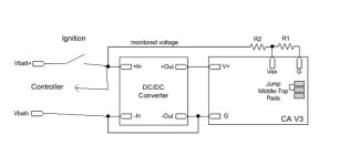
Shut down as normal..keyswitch killing both the controller ignition switch and the DC-Dc convertor powering the CA

After a recharge to 82 volts...from 66.8.....normal CA startup..and i looked at Stats before using the bike..
Cycles still at Zero..despite this being the fourth battery discharge cycle...Total Ah showing as 4 Ah and total mileage as 12 and trip of 1.65...

So not saving even at 15 volt power input.....so does AW have a point about stuff not saving with an external DC-DC PSU running the CA.

Maybe a bigger cap on the output of the DC-DC unit ?
Change the shutdown voltage to a higher level...just below the 15volt of the dc-dc output?
 
NeilP said:
I see that a setting available in the utility is not available on the CA for the PAS settings, namely Quadrature on Dir pad.

this setting does not appear on the CA...
but what ever it is set to within the utility...Quad enabled or disabled, the PAS does not work with the CA reading Rev 9or the utility saying Rev)
Ya - 'Quadrature encoding' was originally available in the CA (for the Thun) but was retired as not offering the advantage originally intended. Subsequently, Justin determined there was value to the mode after all and so it will re-appear in the next firmware release.

Unfortunately, there is a bit of a snafu with the Setup Utility in that it was released with features in anticipation of the next firmware release - which hasn't happened yet. As a result, we have the Quadrature parameter inconsistency and the 'missing parameters' warning. No biggie - just a bit puzzling if you haven't peeked into the CA future... :D
 
NeilP said:
Battery cycles or mileage not saving.

HV setup with 15volt feed to VBatt 1 amp supply

20 s pack 8Ah
...

Maybe a bigger cap on the output of the DC-DC unit ?
Change the shutdown voltage to a higher level...just below the 15volt of the dc-dc output?
Well - I don't like anecdotal evidence for this kind of thing, but FWIW I run my bench ebike simulator with V3 on 4s LiFe and it's been saving data flawlessly for a year an a half (presently working fine at 13.3v).

One requirement is called out in the Guide as:


If you are following this Guideline, then this is a bit of a puzzle.

  • You might try disconnecting the voltage monitor lead to see if you get a reliable data save with the CA remaining powered. This should most certainly be successful.
  • I'm thinking the converter may be dropping out due to falling controller cap voltage before the the requisite CA shutdown voltage is reached to trigger the save. If so, you can raise the shutdown voltage to something a fair bit below your configured LVC but above the dropout input voltage to the converter (e.g. 40v). This will trip the data save on power down as the controller caps discharge far below LVC but before the converter output fails.
If that fails, you might post back and relate how you have the bike main power switch, controller/battery, converter, and voltage monitor (Vex resistor divider) wired up.
 
I'll try that tomorrow...but

Yes, as far as I am understanding the guideline, yes, I am following it.

The controller is permanently wired to the battery

Ignition wire out from controller has permanent battery voltage on.

This feeds the input side of an ignition switch

Output of the ignition switch feeds both the DC-DC convertor the Vex input and back to power on the controller
From my understanding of the guideline , I have followed it exactly.

but I will check in the morning to see I have done it like this. I can't think I have it any other way


wiring.jpg


EDIT
Ummm I am pretty sure I checked the CA plug from the controller...and am sure it does shut down when the ignition goes off....well it has to..that it was used to shut down and de-power the CA .. I moved the red wire from the CA plug from VBatt to the top of the divider feeding Vex monitor point
 
NeilP said:
I will check in the morning to see I have done it like this. I can't think I have it any other way
Okay - hookup looks perfect :D .

Please try the Pref->Vshutdown re-adjustment that is suggested above. The issue may be the same 'falling voltage race condition' described above, but due to converter input caps instead of the controller caps. Here the converter input pins may be holding up the voltage on the Vex divider after the 'ignition' voltage is removed. This will have with the same bad consequences as the converter OUTPUT drops to zero before Vex voltage (coming from the INPUT of the converter) falls to the shutdown threshold...

FWIW: My 10A DC/DC converter has pretty big input caps and throws a big spark on connection just as is normally seen on ebike battery/controller hookup...

NeilP said:
Ummm I am pretty sure I checked the CA plug from the controller...and am sure it does shut down when the ignition goes off....well it has to..that it was used to shut down and de-power the CA .. I moved the red wire from the CA plug from VBatt to the top of the divider feeding Vex monitor point
In my experience, I have only seen the Infineon controller CA-DP red power connection to be tied to the 'ignition' wire so the CA is switched ON/OFF in parallel with the internal controller 5v regulator.
 
Back
Top