The Setup Notes have an Aux Pot Feature section under Advanced Setup Topics and Feautres. Follow the link to the description for wiring a 3-position switch. You can either use the spreadsheets to calculate the resistors you need or tack together one of the first two circuits, tune it, then measure one of the pots and replace it with equivalent resistors that will fit in your housing. Those switches are very cramped - you may find it easier to use the long thin 20 turn trimpots and place them in the CA housing or put them in-line in your switch wiring.bio said:NeeD hElp f0r a Cust0m 3- wAy swiTch!
You are using an out of date browser. It may not display this or other websites correctly.
You should upgrade or use an alternative browser.
You should upgrade or use an alternative browser.
Cycle Analyst V3 preview and first beta release
- Thread starter justin_le
- Start date
teklektik said:The Setup Notes have an Aux Pot Feature section under Advanced Setup Topics and Feautres. Follow the link to the description for wiring a 3-position switch. You can either use the spreadsheets to calculate the resistors you need or tack together one of the first two circuits, tune it, then measure one of the pots and replace it with equivalent resistors that will fit in your housing. Those switches are very cramped - you may find it easier to use the long thin 20 turn trimpots and place them in the CA housing or put them in-line in your switch wiring.
Thanks, but i dont know how to replace the pot i have made a picture of how i think it could be replaced, please correct it if wrong.

This trim pot fits good and just need one and in-line is not looking nice.
Okay - I understand - diagram is fine.bio said:Thanks, but i dont know how to replace the pot i have made a picture of how i think it could be replaced, please correct it if wrong.
This trim pot fits good and just need one and in-line is not looking nice.

Since you want the M setting to be about 50%, R2 and R3 should have the same value. Use a couple of 10K resistors to minimize the effect on your 5K trimpot (a pair of 6.8K, 7.5K, or 8.2K would also be suitable). The 'M' limit % is (R2/(R2+R3))*100 so you can diddle the 50% by playing with the resistors but keep R2 no greater than 10K. See the live limit % on the Setup AUX Pot section title screen as you flip the switch and adjust the trimpot.
mrbill
10 kW
The thought occurred to me that it would be nice if the "aux pot" circuit could alternately function like the "3-speed switch" circuit on the Infineon controllers, where the throttle limits could be set in programming (either through the usual two-button interface or by flashing) rather than having to cobble together resistors and trim-pots. It would be even better if the 3-speed switch discussed could be plugged directly into the CA and used without any hardware modification.
Justin indicates that support for a 3-postion 'Preset Switch' will be coming along. This allows a functionality similar to what you describe using the presets to set the relevant max limit and only requires a couple of fixed resistors across the switch.mrbill said:The thought occurred to me that it would be nice if the "aux pot" circuit could alternately function like the "3-speed switch" circuit on the Infineon controllers, where the throttle limits could be set in programming (either through the usual two-button interface or by flashing) rather than having to cobble together resistors and trim-pots.
teklektik said:Justin indicates that support for a 3-postion 'Preset Switch' will be coming along. This allows a functionality similar to what you describe using the presets to set the relevant max limit and only requires a couple of fixed resistors across the switch.
Comes this with a firmware update (maybe the next) ?
MattyCiii
100 kW
Another small feature refinement/request:
On the "aswvt" cutoffs/summary screen, the "s"/"S" speed cutoff indicator works fine when the upper bound of the speed limit kicks in. It does not however indicate when the minimum speed has not been reached. If possible, please fix this so the "s" becomes an "S" when either speed minimum or speed maximum are being enforced by the CA.
On the "aswvt" cutoffs/summary screen, the "s"/"S" speed cutoff indicator works fine when the upper bound of the speed limit kicks in. It does not however indicate when the minimum speed has not been reached. If possible, please fix this so the "s" becomes an "S" when either speed minimum or speed maximum are being enforced by the CA.
yep - a future firmware update, but it's unclear when.bio said:Comes this with a firmware update (maybe the next) ?teklektik said:Justin indicates that support for a 3-postion 'Preset Switch' will be coming along.
Kepler
10 MW
Looks correct to me.
teklektik said:yep - a future firmware update, but it's unclear when.bio said:Comes this with a firmware update (maybe the next) ?teklektik said:Justin indicates that support for a 3-postion 'Preset Switch' will be coming along.
Ok, i lay may CAv3 in my glass cabinet till the shunt and 3way switch issues get fixed, don´t want make double work.
But i say thanks for your takin the time teklektik.
Pancakebunny
NeilP
1 GW
On Keplers post, what is the last diagramin the image connecting in to the hall wiring achieve?
the bit labelled 5-Y-Speed
the bit labelled 5-Y-Speed
Kepler
10 MW
That would be the hall signal output the CA uses to calculate speed. If you have a CA-DPS, you wouldn't connect this wire.
Kepler
10 MW
Excellent, thanks for that.
The connection may seem obvious to many in thread but I find that a wiring diagam like this makes it crystal clear. Would it be worth adding the diagam to page 17 where all the setup information is located?
The connection may seem obvious to many in thread but I find that a wiring diagam like this makes it crystal clear. Would it be worth adding the diagam to page 17 where all the setup information is located?
Your diagram is controller-specific and there will be similar but different connection points depending on the make and model. The bulk of the controllers using the V3 will already have a CA-DP connector so wiring directly into the controller will not be necessary.Kepler said:Excellent, thanks for that.
The connection may seem obvious to many in thread but I find that a wiring diagam like this makes it crystal clear. Would it be worth adding the diagam to page 17 where all the setup information is located?
That said, this is useful information. You might add a section about Adding a V3-Compatible CA-DP Connector to a Controller to the CA V3 wiki page and add the image there, identifying the particular controller with a paragraph title. The idea would be to have folks add additional paragraphs for different controller make/models.
electricwheels.de
100 W
Hi Justin,
In your Setup Notes for the V3 I read under point 8 f ii:
RPM Cntrl: With this setting, if the user throttle is off but the CA detects that you are pedaling, it will drive the controller with a full throttle output until one of the limit terms is reached.
Here the V3 will go 'full throttle' when the PAS-signal is detected.
European legislation allows the use of a throttle grip only if the rider pedals whilst riding his e-bike.
Now, if you run a powerful System and the V3 will only give 'full throttle', that feature becomes useless if not dangerous.
Instead, the function RPM Cntrl should enable the throttle but OVER THE FULL RANGE, and not just 'full throttle'. Only if the rider pedals, the throttle should become functional in this mode.
This setting could also become dangerous if under certain parameters you happen to flick your pedals backwards - instantly your e-bike will shoot forward! Imagine you are standing at a traffic light or play with the pedals in your lounge room.
Please Justin, change the firmware to this point, or this feature is useless to European riders.
lollandster
10 W
I have been begging for this feature too. Fully working throttle only when pedaling. But do this for torque mode too.electricwheels.de said:Instead, the function RPM Cntrl should enable the throttle but OVER THE FULL RANGE, and not just 'full throttle'. Only if the rider pedals, the throttle should become functional in this mode.
Please Justin, change the firmware to this point, or this feature is useless to European riders.
CA V3 Simple Magura Curve Shaper
The CA V3 closed-loop throttle modes go long way toward refining throttle response, but there always seems to be a request for customizable throttle mapping. Throttle mapping is a more tractable problem with a V3 configured for current (or power) throttle since the mapping from throttle voltage to controller current is forced to be linear by the CA PI control logic. Although active components or a tiny microprocessor are the usual vehicle for developing the throttle mapping curve, V3 configuration features make it possible to implement passive mapping circuits for resistive throttles like the Magura.
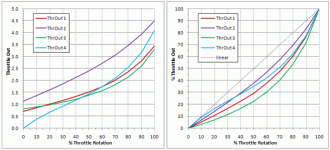
The image on the left below shows simple transfer functions that can be implemented with passive components. Unfortunately, the nature of such passive circuits leaves the output voltage ranges far out of alignment with the controller input range (typically 1v-4v). Although this classically has required active elements to perform scaling and level shifting, the V3 can be configured to accomplish these tasks. Assuming such configuration, the identical curves are redrawn on the right as a mapping of percentage input to percentage output - much more interesting...
These curves were generated using this simple circuit:
Manipulating the resistors has these effects (more or less):
The spread contains four sample designs that can be modified as desired. Here's a summary of the four samples:
View attachment 6
The samples appear on separate worksheets. Here are page images. Simply fill in values in the green cells and the tables and charts will update. The red lines show the actual input to output mapping - output voltage in terms of throttle rotation. The green line in the lower plot shows the output curve (red line) as a percentage of the unmapped linear throttle curve i.e. a comparison of mapped and unmapped outputs. For instance, in the example below, the mapped throttle starts out at about 95% of the unmapped throttle output, dips to 74%, then returns to 100%. (Maybe this curve might be useful for a lower powered DD that needs a little boost at the low end?)
The remaining three samples have increasingly large effect and are designed to illustrate only the range of adjustment - not desirability.
View attachment 4

The shaper is easy to build as a M/F JST throttle adapter. The currents are tiny so power rating is not a consideration - 1/8W resistors were used below. The resistors in the completed adapter can be covered with a few drops of epoxy to bond the connectors into a solid unit.
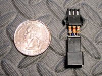
No promises as to the utility of this - either throttle mapping in general or the particular curves this circuit can yield - it seemed an interesting strategy worth putting out there. I personally prefer a 3-position switch to throttle mapping, but some mild mapping may find a way into my bike. I built circuits 2 and 4 above and both worked as expected. Unfortunately, freezing weather prevented all but a cursory test. Something conservative near circuits 1 or 2 might be beneficial for bikes with 3-position switches. Circuit 4 seemed better suited for bikes without speed switches - for instance, at 20% throttle the output is only 5% max. At 3.3kW, the low to mid-range tested pretty well, but the top end was a bit radical. As with any of these mapping 'solutions', you are stealing from Peter to pay Paul - for some part of the throttle curve to be more manageable, another part must suffer.
Anyhow - it's a simple circuit that only costs a few pennies to try - a nice side benefit of the V3.
The CA V3 closed-loop throttle modes go long way toward refining throttle response, but there always seems to be a request for customizable throttle mapping. Throttle mapping is a more tractable problem with a V3 configured for current (or power) throttle since the mapping from throttle voltage to controller current is forced to be linear by the CA PI control logic. Although active components or a tiny microprocessor are the usual vehicle for developing the throttle mapping curve, V3 configuration features make it possible to implement passive mapping circuits for resistive throttles like the Magura.
The image on the left below shows simple transfer functions that can be implemented with passive components. Unfortunately, the nature of such passive circuits leaves the output voltage ranges far out of alignment with the controller input range (typically 1v-4v). Although this classically has required active elements to perform scaling and level shifting, the V3 can be configured to accomplish these tasks. Assuming such configuration, the identical curves are redrawn on the right as a mapping of percentage input to percentage output - much more interesting...

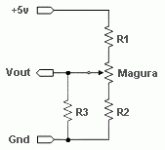
These curves were generated using this simple circuit:

Manipulating the resistors has these effects (more or less):
- R1 is a current limiter used to hold the current to less than 5ma - the recommended V3 max draw for user circuits. Since this current must also power AUX Pot and PAS circuits, conservative power use may be important.
- R2 affects the slope of the curve at ZERO throttle. This is an indirect effect of sliding the throttle ZERO point up and down the transfer curve. Different portions of the curve will have different initial slopes.
- R3 controls the shape of the curve, lower values generally increasing the amount of curvature, higher values flattening the curve toward the unmodified linear transfer function.
- Note: This circuit is not well suited for use with trimpots because of the interactions of the resistances. If trimpots are used then fixed resistors should be added in series for R1 and R3 to ensure that the CA 5v regulator is protected from overload.
The spread contains four sample designs that can be modified as desired. Here's a summary of the four samples:
View attachment 6
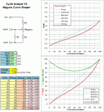
The samples appear on separate worksheets. Here are page images. Simply fill in values in the green cells and the tables and charts will update. The red lines show the actual input to output mapping - output voltage in terms of throttle rotation. The green line in the lower plot shows the output curve (red line) as a percentage of the unmapped linear throttle curve i.e. a comparison of mapped and unmapped outputs. For instance, in the example below, the mapped throttle starts out at about 95% of the unmapped throttle output, dips to 74%, then returns to 100%. (Maybe this curve might be useful for a lower powered DD that needs a little boost at the low end?)

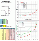
The remaining three samples have increasingly large effect and are designed to illustrate only the range of adjustment - not desirability.
View attachment 4


The shaper is easy to build as a M/F JST throttle adapter. The currents are tiny so power rating is not a consideration - 1/8W resistors were used below. The resistors in the completed adapter can be covered with a few drops of epoxy to bond the connectors into a solid unit.

No promises as to the utility of this - either throttle mapping in general or the particular curves this circuit can yield - it seemed an interesting strategy worth putting out there. I personally prefer a 3-position switch to throttle mapping, but some mild mapping may find a way into my bike. I built circuits 2 and 4 above and both worked as expected. Unfortunately, freezing weather prevented all but a cursory test. Something conservative near circuits 1 or 2 might be beneficial for bikes with 3-position switches. Circuit 4 seemed better suited for bikes without speed switches - for instance, at 20% throttle the output is only 5% max. At 3.3kW, the low to mid-range tested pretty well, but the top end was a bit radical. As with any of these mapping 'solutions', you are stealing from Peter to pay Paul - for some part of the throttle curve to be more manageable, another part must suffer.
Anyhow - it's a simple circuit that only costs a few pennies to try - a nice side benefit of the V3.
hjns
100 kW
Hi Teklektik,
I think this is another great piece of simple hardware, although I do not pretend to understand more than 10% of your post.
Just for my information, in order to experiment with multiple throttle curves in real time, one would have to create multiple of these circuits, right?
And would this also work for the conventional single Hall sensor throttles?
Unfortunately, each change to a resistor value requires recalibrating ThrI->MinInput and ThrI->MaxInput - the price for having the CA do the heavy lifting to make such a simple circuit work. Using longer leads on the JSTs so you could clip in or tack in different parts would work - maybe slipping unshrunk heatshrink over them to guard against shorts. You could use trimpots but adjust them with a meter with the adapter unplugged to get the desired precomputed target values. In any case, playing with the spreadsheet is interesting and recommended to see what's happening...hjns said:Just for my information, in order to experiment with multiple throttle curves in real time, one would have to create multiple of these circuits, right?
And would this also work for the conventional single Hall sensor throttles?
This trick won't work with a hall throttle because R1 and R2 would so reduce the voltage that the sensor would simply stop working.
To be honest, I didn't set out to do throttle mapping - the idea just occurred to me for no particular reason so I ran the spread off and tried it out yesterday for a wintery Saturday project
mrbill
10 kW
Today I did my first moderately long bike ride using the new CAV3. Aside from enjoying a nice warm day in the middle of winter, my objective was to test out this unit and set some of the gain parameters that can only be fine-tuned by testing on the road.
Unfortunately, I ran into some problems, mostly connected with the stored Ah being overwritten or reset randomly.
I wrote up my test on my biking blog:
http://mrbill.homeip.net/bikeBlog.php?latest#skylineBlvd.2013.01.21
But, to keep the record on this forum complete, I'll copy the relevant section below.
Is memory being overwritten or perhaps a problem with EMI causing the CAV3 stored Ah and wh/mi figures to be changed at unpredictable moments during use?
Also, teklektik, can you add a few words about the "Disp Averaging" setting on the "Preferences" setup screen to your Setup Notes? I couldn't find any documentation about it.
Thanks.
Unfortunately, I ran into some problems, mostly connected with the stored Ah being overwritten or reset randomly.
I wrote up my test on my biking blog:
http://mrbill.homeip.net/bikeBlog.php?latest#skylineBlvd.2013.01.21
But, to keep the record on this forum complete, I'll copy the relevant section below.
This first road test of the CAV3 (beta21) revealed a few bugs. Somewhere around the middle of the ride I observed that I had regenerated about 2.1 Amp-hours. Since I have a geared mid-drive, this would be impossible. I can regenerate maybe 100 mAh if I walk the bike backwards quickly, but any more than that is tedious to do. Besides I would have remembered "running" the bike backwards, and on this ride I happen to know that I never got out of the bike.
Later during my ride I started to notice other strange behavior from the Cycle Analyst. One was an instantaneous power reading that fluctuated too much between 200 and 650 watts given a constant throttle and little change in terrain. I stopped and adjusted the sampling rate from "5" to "6"--I'm not sure what these numbers scale to--and that seemed to keep the power figure from jumping around too much, but in hindsight I wonder if this was necessary as the power reading had only just before started to fluctuate.
Then toward the end of the ride I noticed that the Ah displayed was 0.67Ah. The last time I had glanced at the figure it was about 31.3 Ah. I suspect that the stored Ah had been reset or overwritten to zero somewhere around 32 Ah. Oddly, the watt-hours displayed was reasonable, but the wh/mi figure was too low, as if its calculation did not depend on the stored watt-hours and distance that were both showing reasonable figures. The instantaneous battery health display was showing reasonable figures, as was the battery SOC (State Of Charge) indicator on the first screen.
Finally, at the end of my ride the Ah displayed on the first and second screen showed "1.04", but in the trip regen statistics screen, it showed "3.4" forward Ah. I suspect something is randomly overwriting the wrong parts of memory--maybe when Ah rolls past "32", or perhaps a susceptibility to EMI. Tomorrow I will try testing on the bench using a dummy load to see if I can find a pattern to the errors.
Is memory being overwritten or perhaps a problem with EMI causing the CAV3 stored Ah and wh/mi figures to be changed at unpredictable moments during use?
Also, teklektik, can you add a few words about the "Disp Averaging" setting on the "Preferences" setup screen to your Setup Notes? I couldn't find any documentation about it.
Thanks.
Hmmm - I have nothing to offer on this one, but I sent a query off to Justin for clarifiction about this parameter. Will update the doc accordingly. Thanks for the suggestion.mrbill said:Also, teklektik, can you add a few words about the "Disp Averaging" setting on the "Preferences" setup screen to your Setup Notes? I couldn't find any documentation about it.
Similar threads
- Replies
- 0
- Views
- 277
- Replies
- 11
- Views
- 1,189
- Question
- Replies
- 0
- Views
- 869
- Replies
- 2
- Views
- 788
- Replies
- 3
- Views
- 1,192


