OK, I have succeeded where few have tread…
I finally managed to weasel into a 9C RH axel
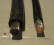
three Teflon-insulated 10-AWG Silver-plated stranded copper wire and
4-pair of 24-AWG stranded (Cat5E) wire
Proof:
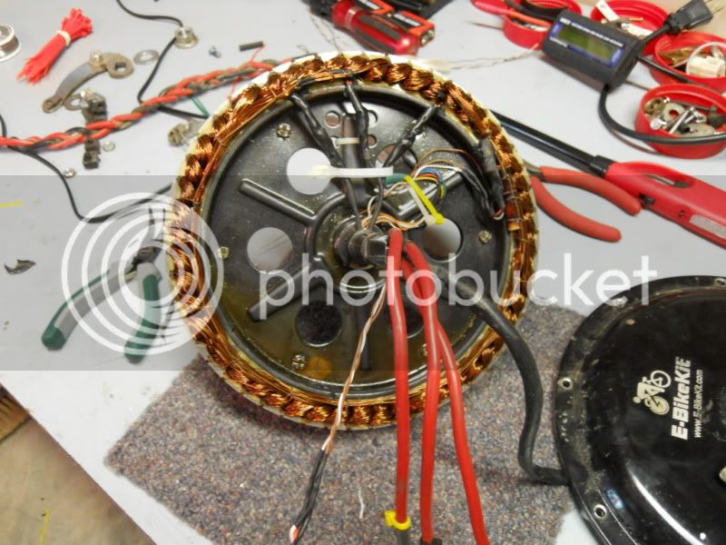
Da big picture...
Purdy-lookin' Cat5E. The hole at the base was opened up.
Looks are deceiving; there is no heat shrink inside the axel: It's just plain wire with insulation. The axel has been bored larger.
This was a
m@$%$%@ f&$#@##$% *&$##@ #^%%^ !#@%^ nightmare! :x I think I wasted enough wire to cable up the Large Hadron Collider. What a complete
B!@#$% to do, and I have zero-desire to do it again. Nope. Gonna do something different for the next wheel.
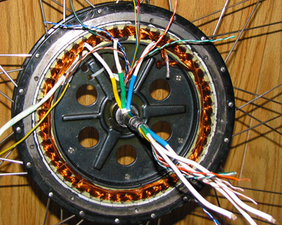
The Cat5E replaces the five wires for Hall Effect sensor wires, plus two for Delta-Wye relays, and 1 spare in case there’s a short.
There were a lot of shorts produced trying to pull these wires through. The trick I used was a LOT of swearing! OK, maybe that didn’t help, but it sure felt good. And I know a LOT of color metaphors from Navy cuss-fights and working down in the engine room.

I tried pushin’, I tried pullin’, I tried splicin’, solderin’, peelin’, honin’, borin’, widenin’, grindin’, flattenin’, squirtin’ and slatherin’. Pissin’ and moanin’ worked best. Yeah… grrr!

I used up more heat shrink than what’s on the rest of the bike! Sorry
liveforphysics; (in my best Elmer Phudd)
I twied and I twied but I just couldn’t get the heat-shrunk wire to pull through without it splitting. Leaving the Teflon on made it more slippery. The toughest part was the overall stiffness of the stranded wire; it was very difficult to work with.
El_Steak has a good concept in his organization; I figured that part out belatedly: The huge problem I consistently had was with the phase and/or wire-pairs getting mixed up and twisted inside the axel.
The last and final time:
- The Cat5E went in first with the cable sheathing intact. Then I pushed in one Teflon phase wire, followed partly with a second. About midway through that push I stopped and pulled the cable sheathing through the axel and off the Cat5 so that the 4-pairs were nicely organized on the bottom. Then I finished pushing the 2nd Teflon wire through.
- At no time did I try to pull the Teflon wires out of the other end of the axel; except for the Cat5 pairs, the other wires remained in the hub butted up at the end. Then I pushed the last Teflon wire in until it too butted up at the base of the hub.
- I used a boat-load of lubrication through the whole process; everything got buttered up with spray silicone and Teflon grease.
- Next I fished out each phase wire out of the pit with various implements until I could get the end pointing upwards, followed by more pushing ~ and that caused the wire to self-curl out of that hole (and repeated for the other two wires).
- I used the meter to identify each teflon wire, checked for shorts, and then put colored heat shrink on the leads.
The next time I do this I will redesign the hub covers and axels to accommodate front disc brakes and 20mm DH forks; The layout is done.
Fracken nightmare.
~
KF grrr


") That is the ultimate for a 9C running stock covers/bearings.
That is the ultimate for a 9C running stock covers/bearings.