Doc's Watercooled Hub motor project ( 5403)

Fello Doctorbass,

Copper is probably a lot easier to work with, and the weight will likely make little real world difference. However, if you ever decide to use aluminum tubing for anything, this site has a list of sizes and all the vendors have these sizes available or they do not get displayed. A lot of aluminum tubing gets used in antenna applications.

http://www.rfcafe.com/references/general/aluminum-tubing.htm
 
Doc did you consider epoxying cover plates to both sides of the stator to create 6 watertight spoke cavities and then plumbing from each spoke cavity to the next? You would have direct water contact with the stator but it would be a lot more water, possibly heavyer than your present plan. Would probably need some sort of baffle in the cavity too.
 
Tom L said:
Doc did you consider epoxying cover plates to both sides of the stator to create 6 watertight spoke cavities and then plumbing from each spoke cavity to the next? You would have direct water contact with the stator but it would be a lot more water, possibly heavyer than your present plan. Would probably need some sort of baffle in the cavity too.


Hi

I considered using these 6 cavities, but the problem is that I wanna have high liquid flow, but I’m limited to ¼ inch tubing size plus their restriction, so the pressure will be really high ( the pump can push up to 50 psi !)

So each cover on these cavity would need to take really big pressure with the epoxy.. and as the temp go high all epoxy are subject to soften.. so this could be a problem…

Or.. maybe I could use some bolt that keep the cover on both side squeezed like a sandwich and use a side cover plate thiocker.. like 3/16 aluminum…or ¼ aluminum

Well this is making me doubt about my actual principle… maybe the sandwich with 6 cavity would be good to…

Well I have to figure out how to build that….. the liquid could travel from the side of one side cover of a cavity to the next like a snake shape …


Doc
 
Hi Doc,

Here is another idea for you... using copper as well.
(all fitting are 3/8" O.D.)

Xlyte 54xx classic Cooling System2.JPG
Xlyte 54xx classic Cooling System_.jpg
 
that's a nice exemple! if only the way to make them would be easy!

Well i think i will try the way of taking the stator 6 branches in sandwich with two aluminum disk and wil make some link between each cavity. By that way, the water to stator interface will be direct. As well the risk of leak is higher, but if i use the dp420 to hold them in place there should be no problem! :wink:


I also found the paint i will use for the motor 8)

I found at Home depot the Rust-oleum COLOURSHIFT :mrgreen: .. that paing change color on different angle of view!.. a bit expensive as well but it will give an awsome look!! http://rustoleum.com/CBGProduct.asp?pid=463


Here is my modified axel:

each bearing are 5mm closer to the center as well as the side cover. I grinded the area on the other side of the axel to have the two brass pipes( made with TV antenna) that will cary the liquid in and out from the stator. The idea of TV antenna tube is that they are thin so i can have the I.D. larger than usual to cary more liquid without having the O.D. too big.

The I.D. is 210mil and the O.D. is 230mil


Doc
 

Attachments

  • P1080939_800x600.jpg
    P1080939_800x600.jpg
    58.1 KB · Views: 4,067
  • P1080941_800x600.jpg
    P1080941_800x600.jpg
    65.2 KB · Views: 4,065
  • P1080946_800x600.jpg
    P1080946_800x600.jpg
    55.3 KB · Views: 4,065
  • P1080947_800x600.jpg
    P1080947_800x600.jpg
    59.2 KB · Views: 4,064
Heck! Don't follow my ideas without careful consideration Doc. It was just that, an idea.
I'm no thermodynamic expert.
Especially as you've put so much effort into the copper heat exchanger.
PS: like the axel mod.
 
nicobie said:
Axle mod looks great.

How are you going to get the bearing over the water pipes?

The I.D. of the bearing and the output tubes fit just perfect!

Doc
 
Doc,

I find it difficult to believe that you're going to all this trouble, and even pressed out the axle, yet you're further weakening an already proven to be inadequate axle, and putting it back in the motor instead of replacing it with a larger stronger axle with more room for the things you want to run through it. The only other change would be going to bearings with a larger ID.

Be careful.

John
 
auraslip said:
I think enlarging the bearing ID would require some pretty nifty tools. Any thoughts on that?

Yes, the easy way...get a bearing with the same OD and a larger ID to fit the new shaft. Xlyte bearings are crap and need replacing anyway, so just get a different size.
 
John in CR said:
Doc,

I find it difficult to believe that you're going to all this trouble, and even pressed out the axle, yet you're further weakening an already proven to be inadequate axle, and putting it back in the motor instead of replacing it with a larger stronger axle with more room for the things you want to run through it. The only other change would be going to bearings with a larger ID.

Be careful.

John


Hi John,

I still always appreciate pros and cons about any idea i have and you are always the one that is more critic about these idea.

That make me thing a bit more about these so i like that as well.

The axel are innadequate for poople who dont understand how torque work on metal part... if you use a little bit of mechanical engineering it's easy to know how to use it without having problem.

Remember i have 5 X5 motor and am also one of the person who have put the most kW into them and torture test them more than enough... and... i NEVER had any failure... ( i have all existing generation of X5 too)

I never twisted any axel and i doubt i could have problem doing it. The torque arm i make are also a good match to avoid any metal torsion or shear.
I will put back teh axel with the DP420 epoxy wich will be very strong so the stator wont turn on the axel.

The idea of making a new axel would cost me $$$ and i dont have any source for having a custom made axel for cheap. So i have to keep the original axel

I abandoned the idea of cooper tube and will concentrate on the aluminum disk that take the 6 cavity in sandwich.

I already machined the two disk and the stator border seat to fit them

I will use the epoxy DP420 too to fix them

Doc
 
John in CR said:
auraslip said:
I think enlarging the bearing ID would require some pretty nifty tools. Any thoughts on that?

Yes, the easy way...get a bearing with the same OD and a larger ID to fit the new shaft. Xlyte bearings are crap and need replacing anyway, so just get a different size.

I had no difficult machining the larger hole for the 6005 bearing on the side cover that had the 6004..

It only take patience..

Doc
 
Here is the new concept some Tom L suggested and that i decided to adopt and to modify a little bit.

That's the stator sandwich cooling concept!


Now i need to determine the path i will add to have the liquid circulate in the cavities to maximize the heat exchange and the pressure drop to be minimal

Doc
 

Attachments

  • P1080948_800x600.jpg
    P1080948_800x600.jpg
    104.3 KB · Views: 4,015
  • P1080949_800x600.jpg
    P1080949_800x600.jpg
    61.6 KB · Views: 4,015
  • P1080950_800x600.jpg
    P1080950_800x600.jpg
    46.9 KB · Views: 4,013
  • P1080951_800x600.jpg
    P1080951_800x600.jpg
    79.7 KB · Views: 4,014
  • P1080952_800x600.jpg
    P1080952_800x600.jpg
    61.5 KB · Views: 4,014
  • P1080953_800x600.jpg
    P1080953_800x600.jpg
    76.4 KB · Views: 4,015
  • P1080954_800x600.jpg
    P1080954_800x600.jpg
    79.5 KB · Views: 4,015
I like that approach for liquid cooling a lot. The axle I don't like, and all respectable hubbie manufacturers would agree for motors rated at 1500W or higher.
 
Here is a better representation that Bison_69 did for me by the free time he had :wink:

The only difference is that on the version i'll make, there is only the liquid link on ONE disk.

This is in progress. :wink:

Doc
 

Attachments

  • Xlyte 54xx classic Cooling System Assy2_1_800x528.jpg
    Xlyte 54xx classic Cooling System Assy2_1_800x528.jpg
    38.5 KB · Views: 3,703
  • Xlyte 54xx classic Cooling System Assy2_2_800x528.jpg
    Xlyte 54xx classic Cooling System Assy2_2_800x528.jpg
    40.6 KB · Views: 3,703
  • Xlyte 54xx classic Cooling System Assy2_3_800x462.jpg
    Xlyte 54xx classic Cooling System Assy2_3_800x462.jpg
    26.1 KB · Views: 3,703
  • Xlyte 54xx classic Cooling System Assy2_800x528.jpg
    Xlyte 54xx classic Cooling System Assy2_800x528.jpg
    36.5 KB · Views: 3,702
  • Xlyte 54xx classic Cooling System Assy2__800x528.jpg
    Xlyte 54xx classic Cooling System Assy2__800x528.jpg
    44.2 KB · Views: 3,702
awsome work.. well done !!

but i'm a bit torn in my opinion, if you are making that much heat, why just not use a bigger motor and put that energy to use.. ?

I'm running an x5305 in a 20" rim on my trike, at 72v and 60 or so battery amps, the motor and controller are barely warm after my ripping donuts and start/stop low speed full throttle runs... that's 5000w used efficiently..

X5's at over 10,000w are doing nothing but producing heat... if you want more go.. get a bigger motor.. imo.. :|
 
Ypedal said:
awsome work.. well done !!

but i'm a bit torn in my opinion, if you are making that much heat, why just not use a bigger motor and put that energy to use.. ?

I'm running an x5305 in a 20" rim on my trike, at 72v and 60 or so battery amps, the motor and controller are barely warm after my ripping donuts and start/stop low speed full throttle runs... that's 5000w used efficiently..

X5's at over 10,000w are doing nothing but producing heat... if you want more go.. get a bigger motor.. imo.. :|


I agree Ypedal, The goal is to keep that efficiency high at anytime. As the motor run, it heat up... and when it heat up, the winding resistance increase by a significant factor.. and as it increaser it produce more heat.. and that loop continu...

On my motor, when the motor is cold, it is like two time more powerfull than when it is hot ( 100 degree C on the winding and up.

the idea is to keep the temp low to preserve the same efficienct and power as when the motor is cold.. or .. not hot

I'm really confident that the 24W liquid pump consumption will be largely compensated by the efficiency gain!!

Doc
 
i like the new approach alot less weight and direct contact patch with the fluid and the stator center..
what about just pumping air through this new approach it will have great cooling benefits and no liquids or radiator needed so would be much lighter, you could add copper heatsinks between the spokes of the stator to get more surface area..
the stator center is made out of cast steel right, why not get some aluminum billet and make one like the dual pie setup someone on here made, could be made much lighter, better conductivity and you can channel the fluid/air as close to the edge of the stator as you want and do a crazy maze sort of effect to get more surface area just like they do in car gearboxes..

i guess these ideas are alot of $$ and effort but im just putting them out there as they are in my head, and possibly something to build onto.. brainstorming..
 
Update!!

More parts finished... Damn.. I can not use the lathe at my work.. i dont have the permission and the switch have a lock on it... :roll: .. But i use it anyway with a lithium cordless drill connected to the end of the lathe axis to make it rotate and it work! :mrgreen: .. So i machined some circular parts for some new features for the liquid path in the stator. 8)

The new desing use the center of the 6 branches of the stator core and liquid that circulate in the 6 cavity... BUT.. I also will have the liquid to circulate along the circunference of the stator aluminum parts.. on both side!! wich will increase by 750% the heat transfer! I will add tomorrow the aluminum ring that will seal the two disk so the liquid will circulate on both side o fthe stator and on teh center 8)

Some pics for you again:
 

Attachments

  • Picture 004.jpg
    Picture 004.jpg
    79.5 KB · Views: 3,860
  • Picture 006.jpg
    Picture 006.jpg
    74.8 KB · Views: 3,859
  • Picture 019.jpg
    Picture 019.jpg
    110.3 KB · Views: 3,859
  • Picture 013.jpg
    Picture 013.jpg
    54.1 KB · Views: 3,859
  • Picture 012.jpg
    Picture 012.jpg
    37.8 KB · Views: 3,860
  • Picture 021.jpg
    Picture 021.jpg
    84.5 KB · Views: 3,860
Oh i forgot.. here is the liquid path:
 

Attachments

  • liquid path.JPG
    liquid path.JPG
    123.3 KB · Views: 3,855
Beautiful work!

I hope the windings transmit the heat fast to the aluminium core. Have you already think about using some thermal compound to improve the thermal transmission from the coils to the aluminium core?
 
Such an ambitious project, agreed with even if you got a bigger motor you would want to do this to it too. Your thirst for ebike power is unquenchable.


I love how you take aboard suggestions, Always have.

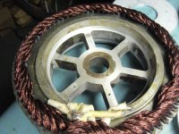
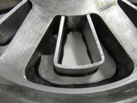
The copper pipe IMO was a great idea, as the fluid remains in the same volume and wont expand, turn into steam inside as easily. The way around this is using higher pressure pump, and estimate the heat/expansion and the pressure and flow required to avoid steam within that inner increased volume.. it was a good idea to keep the size uniform because Im not sure how well steam cools. But the new suggestion, looks like it can work better.

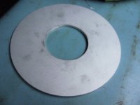
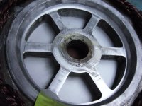
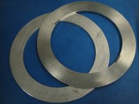
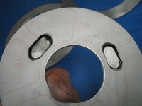
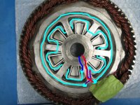
Also. It may be better to have the cooler water entering around the outside path first and draw the heat inwards away from the coils, this outer coolant path is at least restrictive and the inner path is less hot with lots of area and may avoid coolant expanding too much. You could heatsink glue and metal glue combination some aluminium heats sinks on both sides of the plates, low profile heat sinks all over outside plates, increase the surface area to take advantage of airflow, and onto inside plates within and along, the inner path to draw some heat towards the plates where you have the low profile heat sinks. The inside heat sinks would decreasing the volume of the inner coolant path a little, but make it not more restictive than your inlet and oulet pipes.

Ive used that metal epoxy together with, normal heat sink paste with very high powered leds, I place an area of paste in the middle of the heat sink contact point I want, leaving a clean borarder area around the heat paste, and use the metal epoxy glue around the outside of the paste, hold it down with clamp for a few hours till the epoxy hardens. Makes it solid as a rock on viagra and water proof,Works vey well.

I just put the paste on the led, place the led where I want it on the heat, sink push hard to spread the paste, and pull it off and clean the area I want to add the epoxy, add epoxy, put the led back into place, and calmp. You could do the same thing with your plates.


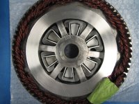
I believe if you can get rid of as much heat from within, making the motor still capable of getting rid of heat by its self, the less power you will require on the external cooling parts, basically all over more efficient.. Why not take advantage of the air flow and water before the water leaves the motor too.

I ran this simulation of this design in my head a few times, the coolant from the radiator to motor is the coldest, I just feel if inside path coolant gets hot you will lose the effect of coldest water where you may need it. And the outside path clostest to the coils is best to avoid getting hot first place.
 
UPDATE 3 june:

hand craft parts finished, almost all parts are glued together.

80% done !

This is very encouraging!

[youtube]C0aRmSR4a8o[/youtube]


Doc
 
Back
Top