Doc's Watercooled Hub motor project ( 5403)

gensem said:
Maybe its the copper fill on the cromotor that make up for one more turn.

Doc whats the winding on the the 5403, like 20 x 3 or something like it?

5403:

-winding:
--number of strands: 8
--size of each strands: AWG 20 (0.032'")
--All strands = to one AWG 11 conductor
--inductance between two phase wire: 297uH
--DC resistance between two phase wire: 0.104ohm

-number of pole: 12
-number of magnets: 24


compare to the 5303:

5303:

-winding:
--number of strands: 8
--size of each strands: AWG 20 ( 0.033"dia)
--All strands = to one AWG 11 conductor
--inductance between two phase wire: 169uH
--DC resistance between two phase wire:0.097ohm(direct to winding) and 0.103ohm(thru the anderson connector)

-number of pole: 12
-number of magnets: 24


It's same winding but more copperfill
 
zombiess said:
gensem said:
Maybe its the copper fill on the cromotor that make up for one more turn.

Doc whats the winding on the the 5403, like 20 x 3 or something like it?

Would copper fill effect the KV? I'm no motor expert, I'm curious because the little I do know stats that when you double the stator width and keep the same number of winds (with everything else the same) the KV gets cut in half.

Anyone know the inductance of a 5403 or 5404? I kind of wish I had one to play around with myself simply for the sake of experimenting. Can't wait until it cools off and I can start playing around with my bikes some more.

Inductance is 297uH between two phase wire
 
Doctorbass said:
Inductance is 297uH between two phase wire

Is that the inductance with the stator in the magnet ring our out of the magnet ring? I measured the inductance of the 4 turn Hubzilla around 120uH in the magnet ring. I haven't pulled one out to measure it by itself. If you can, would you measure it again in the magnet ring?

I'm trying to get a better understanding of the differences in these motors since these are the two biggest bad boys available to easily fit into a bicycle. This is not sales crap from me, that would be lame, I'm genuinely interested in learning here on the differences and what makes things tick.

I really have to commend you on your work. It looks top notch and I can't wait to see how far you can push this motor. I hope you can push this thing into saturation (or at least figure out where the point starts) and reach 88mph :mrgreen:
 
zombiess said:
Doctorbass said:
Inductance is 297uH between two phase wire

Is that the inductance with the stator in the magnet ring our out of the magnet ring? I measured the inductance of the 4 turn Hubzilla around 120uH in the magnet ring. I haven't pulled one out to measure it by itself. If you can, would you measure it again in the magnet ring?

I'm trying to get a better understanding of the differences in these motors since these are the two biggest bad boys available to easily fit into a bicycle. This is not sales crap from me, that would be lame, I'm genuinely interested in learning here on the differences and what makes things tick.

I really have to commend you on your work. It looks top notch and I can't wait to see how far you can push this motor. I hope you can push this thing into saturation (or at least figure out where the point starts) and reach 88mph :mrgreen:


Yes the 296uH is with the motor assembled and ready tu use... remember the inductance is measured between two phase wire that are connected in star.. so it's like two independent inductance in serie... since it's connected in star.. so each seperate phase have half that

Doc
 
So what would cause the Hubzilla motors have such a much lower inductance? What makes both of these motors so different in inductance and the KV of a 5403 not much faster? Any ideas? I have a 2 turn version that is 17kv but the inductance is about 40uH.

Does a 5404 have an inductance around 400uH, both numbers seem really high for the motors. Looking at bigmooses spreadsheet makes it look like higher inductance means the motor saturates at a lower point. Id like to see someone else measure the inductance to see if their numbers match yours. Someone told me that the hubzilla was 275uH but when i measured several of them they all came out to around 120uH. Maybe the other person measured it out of the magnets.

I was guessing a 5403 would be much lower. Do you have a 530X you could measure the inductance on? Id be really interested to see what the different windings measured. I need to go check my 9c 2806 and 2808.

I wonder if the greyborg motors are in star or delta now after your comment about star in series. Any easy way to tell?
 
zombiess said:
So what would cause the Hubzilla motors have such a much lower inductance? What makes both of these motors so different in inductance and the KV of a 5403 not much faster? Any ideas? I have a 2 turn version that is 17kv but the inductance is about 40uH.

Does a 5404 have an inductance around 400uH, both numbers seem really high for the motors. Looking at bigmooses spreadsheet makes it look like higher inductance means the motor saturates at a lower point. Id like to see someone else measure the inductance to see if their numbers match yours. Someone told me that the hubzilla was 275uH but when i measured several of them they all came out to around 120uH. Maybe the other person measured it out of the magnets.

I was guessing a 5403 would be much lower. Do you have a 530X you could measure the inductance on? Id be really interested to see what the different windings measured. I need to go check my 9c 2806 and 2808.

I wonder if the greyborg motors are in star or delta now after your comment about star in series. Any easy way to tell?
Dont forget that the inductance will change with the rotor presence or not and also that number depend on WHERE you take the measurement.. is it between the tap and one of the 3 other wires or between two wires that are joined with the tap ( in normal star mode)


look like that the value you have and the otehr value someone else measured are like double.. this could be explain the two phase in serie and not the phase to tap point...
 

Attachments

  • Star hub inductance.JPG
    Star hub inductance.JPG
    24.7 KB · Views: 3,686
I know what you are saying and I averaged out several positions to get the values I posted. I'm just wondering if there is an easy way to determine if the motor is wired in star or delta without ripping it apart. I'm surprised by there being such a large difference in inductance between two similarly sized motors.

BTW, did you get your high speed wind? If so are you planning to try and water cool that? :mrgreen:
 
Zombies,
You'll have trouble with such direct comparisons due to the very different slot and pole count, along with the drastic difference in how the windings are done.
 
Motor pimp 100% finished

:mrgreen:

I just have now to install it on the Giant and also the radiator and pump and put some 50% premix into it, bleed it and that's it ! :twisted: :twisted: :mrgreen:

Here is the motor mounted with strong 12 gauge spokes and the last Doubletrack 24" 36h on earth! and a maxxis hookworm

I can say that this beast will be probably the most powerfull Crystalyte hub motor ever made :wink:

Doc
 

Attachments

  • P1090083_800x600.jpg
    P1090083_800x600.jpg
    153.5 KB · Views: 3,581
  • P1090084_800x600.jpg
    P1090084_800x600.jpg
    153.7 KB · Views: 3,581
  • P1090085_800x600.jpg
    P1090085_800x600.jpg
    169 KB · Views: 3,581
OK, I came in late here, so going back to the axle a bit. I do hope you are correct and I am wrong, but I still have big concerns about the axle..especially after all the amazing work you have done on the rest of the motor. Would be such a shame to now see it fail because of the axle breaking

John in CR said:
Doc,

I find it difficult to believe that you're going to all this trouble, and even pressed out the axle, yet you're further weakening an already proven to be inadequate axle, and putting it back in the motor instead of replacing it with a larger stronger axle with more room for the things you want to run through it. The only other change would be going to bearings with a larger ID.

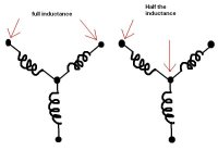
Doc, I agree with John, to a degree. I do not think that what you are doing will weaken the axle any further, What you are doing could be said to be rather like having a power line with two fuses in series with it...what you are doing is changing a 13 amp fuse for a 10 amp fuse, but the second fuse in series is only a 5 amp anyway, so yes the slot is weakening it, but the shoulder where the threaded portion starts is far weaker anyway, so making a new slot is not going to cause any problems.


Doctorbass said:
The axel are innadequate for poople who dont understand how torque work on metal part... if you use a little bit of mechanical engineering it's easy to know how to use it without having problem.

I am trained as engineer..to basic level...( one year diploma) and do understand these things...I had a problem with my axle fully clamped in torque plates.


Doctorbass said:
Remember i have 5 X5 motor and am also one of the person who have put the most kW into them and torture test them more than enough... and... i NEVER had any failure... ( i have all existing generation of X5 too)
I never twisted any axel and i doubt i could have problem doing it. The torque arm i make are also a good match to avoid any metal torsion or shear.

As you see mine twisted clean off...5700 miles or so...Not as much power as you .. I see continuous of about 5kW...for a minute or so...and peaks of best so far 14.2kW. Also heavy regen breaking. It is not the interface between torque plate and axle that is the problem, it is the stress point at the shoulder where the axle drops down to 14mm, that is where mine twisted. My drop outs were tight also, so I effectively had a torque plate of the thickness of my plates, plus the dropout thickness, so ...15-18mm thick right up to the shoulder. Maybe you got lucky with the steel your axles are made of..maybe I just got the Friday axle...


Doctorbass said:
I will put back the axel with the DP420 epoxy wich will be very strong so the stator wont turn on the axel.
I am putting heavier splines on mine...but I I may use this epoxy too. or I may just drill and pin at the spline junction with hardened roll pin


Doctorbass said:
The idea of making a new axel would cost me $$$ and i dont have any source for having a custom made axel for cheap. So i have to keep the original axel
I have a mate with a big lathe and milling machine :D


Did you see the picture of my breakage? The axle did not break at my torque plates, there was no movement of axle within the torque plates, mine snapped at the the 14mm shoulder where the threaded portion ends, about 12mm in from the the torque plate.
It was a clean break, no old rust in fracture, it happened instantly ..back wheel came off as I pulled away.
The thread is here here

and here are my pictures of the break, annotated by Big Moose
file.php

file.php


OK, so if you get lucky and do not have big crystalline structures in your axle then you may be OK, but I reckon you should do something about the threaded end.

Like this, then you can make full on clamping torque plates

View attachment 4
2.jpg
3.jpg
View attachment 1
5.jpg

If you could then heat treat to reduces stresses etc then even better
 
ohzee said:
Is it purple or blue ? (Nice paint) Anyway it sure is sexy.. can't wait for the test drive.


It's colorshift from Rust-oleum !.. it change depensing on the angle 8)

DOc
 
The good news is that axle failure is more likely to occur at low speed(unless insanely powerful regen is applied at 90mph), so if in 5500 miles it is more prone to failure, at least he will get back up and walk just like you did. Doc, update?
 
NeilP and John, Thanks guys for your advices.

I'm sure that if the torque is equally shared on both torque arm ( both side of the axel) and that the distance of threaded axl with the nut is not too fat, the twisting effect is minimal. I never had any problem with that wilh all my 5 X5 motors and you know how much power and abuse i make with that.

My torque arm are the key to minimize axel twist.

When the metal shear where the threaded axel junction is, it'S because of bad torque arm, over thightened axel etc.. Mine dont need to be alot thightened.. just enough to hold the wheel in place from falling... not more.. so the stress on the axel is decreased.. ( no tensile stress.. only shear stress)

I tried it today at FULL power with my kelly 120V 220A and removed the motor to check.. and i have no deformation sing at all.. and usually all my motor that can take abuse like that are still working today .. after 5 years of fun ( since 2007) :wink:

Doc
 
I definitively feel the difference from the old 5303.

The torque difference is amazing!!

But the radiator and pump was not installed so i decided to not abuse it from now

I will install everything tomorrow

Doc
 
Doctorbass said:
I'm sure that if the torque is equally shared on both torque arm ( both side of the axel) and that the distance of threaded axl with the nut is not too fat, the twisting effect is minimal. I never had any problem with that wilh all my 5 X5 motors and you know how much power and abuse i make with that.

My torque arm are the key to minimize axel twist.

When the metal shear where the threaded axel junction is, it'S because of bad torque arm, over thightened axel etc.. Mine dont need to be alot thightened.. just enough to hold the wheel in place from falling... not more.. so the stress on the axel is decreased.. ( no tensile stress.. only shear stress)

I tried it today at FULL power with my kelly 120V 220A and removed the motor to check.. and i have no deformation sing at all.. and usually all my motor that can take abuse like that are still working today .. after 5 years of fun ( since 2007) :wink:

Doc

Well I do understand what you are saying, but there is no way my torque arms cold be considered as bad in anyway. My torque arms are more than adequate, that was not the issue, there was no flexing, twisting or movement of the axle within the torque plate. The axle was clamped solid, and the wheel nuts torqued to a low figure, seem to remember 40 ft lb was the figure I used,would need to check at the workshop and my note book to see what figure I used.
The recommended figure for low grade steel bolts is around 60ftlb for 14mm. up to around 160 for higher grade tensile bolts. The nuts were full size, not nyloc, so as to maximise the amount of thread contact, and a bolt adhesive was used.

On inspecting the threaded portion, I can confirm that there is no more deformation on the section that was within the torque plates and rear dropout than there is on the new axle that I have received from Kenny last week. I guess maybe I just was unlucky then

If you have not had any issues, then maybe I just got unlucky with mine
 
Doctorbass said:
Motor pimp 100% finished

:mrgreen:

I just have now to install it on the Giant and also the radiator and pump and put some 50% premix into it, bleed it and that's it ! :twisted: :twisted: :mrgreen:

Here is the motor mounted with strong 12 gauge spokes and the last Doubletrack 24" 36h on earth! and a maxxis hookworm

I can say that this beast will be probably the most powerfull Crystalyte hub motor ever made :wink:

Doc

Doc your work is awsome, i can't belive the quality effort you put into it.

you should be able to maintain 10kw continious IMO with a good water cooling system & of course the air cooling also!!!!

throw the kelly controller on it and bring it to the track, make sure you pertty much glue the axle to everything... stator, the bike frame lol... don't worry about changing tire... but keeping tire on back of frame lol

-steveo
 
doc did you get the water flowin on this thing yet?

-steveo
 
steveo said:
doc did you get the water flowin on this thing yet?

-steveo


Still no water flowing in.

I did not have time to install teh radiator and pump yet...

But i can say that this motor is really cold compare to the 5303!!!

The max temp i got is 101 celsius on the winding!!... with 260A 115V burst 8)

The only problem i have now is that when i go WOT from a dead stop, the motor seem to have some power glitch between the 30-70% speed/power range.... Just like if the Kelly controller is reaching the power limit and cut by pulsating fast the current.. just like "Brrrrrrrrt"

but is i slow down the throttle a bit, it doesn't and is ok...

i'll play with the Torque/Speed/Both mode and themotor current and battery currernt to find that problem...

I wonder if it could be the hall sensor wires having interference with the hase wire high current making parasitic signal by induction.... and if it would require that i shield them with some copper braid...

well i have some test to debug that.. otherwise i can say that the power is awsome!... at 80kmh the front wheel wanna lift easy if i dont pay attention to put my weight on the front!!

I think that the watercooling will be helpfull during the intense abuse like offroad or things similar like the pike peak hill climb...


Steveo, btw, who is the best person i should contact to rosspar for a new connector order? ( PM me)

Doc
 
hillzofvalp said:
But how many watt hours did yoU put through to get that temperature


30s lipo 15Ah

about 1400Wh (80% discharge max)

but i did not measured how many Wh i need from a full battery, cold motor and WOT hill climb until motor get that temp...

Could be interenting to test :wink:

Doc
 
Wh/mile or Wh/km is the important measure of how much power you're running through a motor for comparative purposes, and especially useful if you're able to run WOT. The only place I can stay at WOT for more than a few seconds is on the highway. The hills are all too curvy here for WOT.

Sorry to hear the Kelly is having problems. You should get SteveO to do you up a controller. The 36 I'm running at 425A battery 550A phase limits is from him.

with 260A 115V burst

At what speed did you hit peak current? I hope you're not still quoting that 0-1rpm stuff. Ease up to 15-20kph and then go to WOT and let us know AMAX and VMIN.

And get that coolant flowing.

John
 
Back
Top