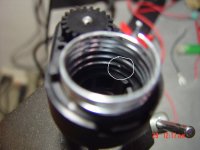
Dogati Electric Superleggera

j3tch1u said:
rebelpilot said:
j3tch1u said:
who wants to join the Dogeratti? 8)
Me :D

that's it? guess it's just you and me then rebel :lol:

Im in....need a crane to get me up on a Dogati but yes, im definitely in mate :lol: :mrgreen:

KiM
 
rebelpilot said:
AussieJester,
The seat looks as though it could be modified to hoist you up from behind the bike :D


oooh yes i like the soound of that :idea: someone breakout the AutoCAD please LoL..

KiM
 
AussieJester said:
Im in....need a crane to get me up on a Dogati but yes, im definitely in mate :lol: :mrgreen:
KiM

kim, the motorcycle stand can be modified so that the rear wheel is touching the ground (the bike is still supported by the rubber feet on the dropouts). this should give you enough stability to slide onto the bike with the seatpost in the front-tuck position. at this point you could simply launch off the stand. egress could be a challenge though. the front-tuck seat position is actually really great for take-off's--keeping as much weight over the front wheel to fight the wheelie.
 
Yeah, I certainly want one in my stable! I would want a few changes though, just cause I like stuff different.

I hope to see you get this into production! How awesome would it be to see one of these going down the road in the US!
 
johnrobholmes said:
Yeah, I certainly want one in my stable! I would want a few changes though, just cause I like stuff different.

I hope to see you get this into production! How awesome would it be to see one of these going down the road in the US!

modding is what i had in mind for the end user--helps absolve me from liability in a court of law haha. the production version may have different bike components (options) depending on what i can source from local oems (usually still name brand stuff). retail on bike parts are pretty high above cost.

i'd like to see these on us and euro roads as well. however, the corp registration will be as far away from this great litigious nation of ours :p
 
GGoodrum said:
Put me on the list, as well. :) These will be true works of art, for sure.

-- Gary

hi gary! now i'm going to look really bad if i don't deliver :oops:

speaking of works of art, i happen to be assembling your v4.2.6 cell-log bms right now. i like the idea of the programmable hvc/lvc cut-offs. the form-factor is a tad smaller than the 2.6 boards which is nice cuz i had virtually zero clearance at the front of the frame where it gets narrow. my backing board also makes a nice heatsink for the shunt resisters. do you plan on continuing this line? an smd cell-log bms /w "by exception" shunting would be killer! :wink: :wink:

gonna be taking apart the battery to route the alarm wires. while i'm at it, i'd also like to figure out a nice way to turn off the bms and cut off the taps without adding a million switches. i don't use a controller switch or pre-charge resistors (just the marine breaker). sometimes i forget to energize the esc before connecting the taps--would rather that they could just remain attached.
 
j3tch1u said:
GGoodrum said:
Put me on the list, as well. :) These will be true works of art, for sure.

-- Gary

hi gary! now i'm going to look really bad if i don't deliver :oops:

speaking of works of art, i happen to be assembling your v4.2.6 cell-log bms right now. i like the idea of the programmable hvc/lvc cut-offs. the form-factor is a tad smaller than the 2.6 boards which is nice cuz i had virtually zero clearance at the front of the frame where it gets narrow. my backing board also makes a nice heatsink for the shunt resisters. do you plan on continuing this line? an smd cell-log bms /w "by exception" shunting would be killer! :wink: :wink:

gonna be taking apart the battery to route the alarm wires. while i'm at it, i'd also like to figure out a nice way to turn off the bms and cut off the taps without adding a million switches. i don't use a controller switch or pre-charge resistors (just the marine breaker). sometimes i forget to energize the esc before connecting the taps--would rather that they could just remain attached.

Since you are going into low-rate production, we could do a board more specific to your needs. For instance, I had versions previously that had built-in FET switches that would cut power to the CellLogs unless either the charger was connected, and on, or if the controller is on. We could do something similar here. Also, the cell circuits don't need to be disconnected. The standby current draw is something like 10 uA.

Are you planning on sticking with the same cell type? I think you were using a 16s setup of the a123 pouch cells, is that right? I can't remember now. Anyway, I'd really take a look at switching to LiPos. Better energy density and whole lot cheaper. :)

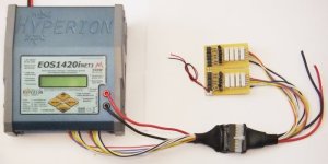
I've pretty much gotten away from any sort of onboard cell balancing for my setups now. Instead, I just do cell-level LVC protection, and then bring out a single multi-pin plug that has the balancer connections and the main charge leads in one connector. I then use a matching plug that has the required charger connections. There are lots of higher-end RC chargers available now that can handle 10+ cells. The Hyperion 1420i I use with my 12s LiPo packs has 14 channels. The nice thing about these is it will accurately charge and balance a pack every time in pretty much the same amount of time as a bulk charge alone.

12s Charging Harness Kit-22.jpg


Anyway, we can do whatever makes sense. Email me with what you think you need.

-- Gary
 
gary, my thoughts (nothing set in stone): for a consumer oriented product i would offer a big (1000w) cccv charger--plug and play with no settings to mess with. the ng1 is nice and maybe that could be a high-end option. ideally most of the logic would be on-board the bms--one board, one point of failure. the bms should probably be smd and relatively easy and cheap for us to swap/replace if it fails. it would also be nice to integrate the guts of a small 100w meanwell on-board for opportunity charging--in-the-wild plug-n-play.

yes, i'm currently using the a123 15ah prismatics (16s). however, i may need to find an alternative (and change the pack design) since i'm not sure i can source these cells. for my own personal bike i would go with lipo. however as a consumer product, lipo, a dual hyperion charging system and series/parallel switching just puts too much faith in the end-user.

your bms with the fets for switching bms, controller, charger(s) etc would be ideal. this is really beyond my area of knowledge and i really appreciate your generous help. looking forward to discussing with you further. maybe next time you are in thailand, you could swing by taiwan!
 
The DeltQ (http://www.delta-q.com/products/quiq.shtml) or Elcon (http://www.elconchargers.com/index.html) look about identical to the Zivan. I think they all come out of the same factory. The newer versions of these have a BMS interface that supports linear throttling and makes the BMS part much simpler. Older versions will still work, but cycle on and off during balancing if a cell goes high enough to trigger the HVC. It still balances, but will take a bit longer if the cells are way out of balance.

An on-board Meanwell might be a bit harder to implement, depending on the rating. One thing is they need a series diode or line powered relay to disconnect the charger when off or it will slowly drain the pack. If the current is limited to something below what the shunts can handle, then no HVC interface should be needed.
 
I agree with Richard that using something like the DeltQ or Elcon would be ideal, because it would really simplify the BMS control logic. Not sure how we'd make a cloned MW fit either.

The basic BMS design is the same, whether you use LiPo or LiFePO4. All that changes is a couple parts per channel. If you want this turnkey, I'm assuming the CellLogs go away as well, is that right? We can do it either way, but without is simpler.

Richard and I have been wanting to do a surface mount version for some time now, but we've not really had a stable design until very recently. If we do it here I'd like to do it in a way that we can make this a bit more general purpose, so it can have a wider use. Basically, it is more about the number of channels. If you find another source, and stick with LiFePO4, 16 channels would be the baseline, of course, but I think I'd do the board so that it might have a "tearoff" section of 8 more channels, so in it's full version, it could support 24 channels. Lots of options here.

-- Gary
 
GGoodrum said:
I agree with Richard that using something like the DeltQ or Elcon would be ideal, because it would really simplify the BMS control logic. Not sure how we'd make a cloned MW fit either.

The basic BMS design is the same, whether you use LiPo or LiFePO4. All that changes is a couple parts per channel. If you want this turnkey, I'm assuming the CellLogs go away as well, is that right? We can do it either way, but without is simpler.

Richard and I have been wanting to do a surface mount version for some time now, but we've not really had a stable design until very recently. If we do it here I'd like to do it in a way that we can make this a bit more general purpose, so it can have a wider use. Basically, it is more about the number of channels. If you find another source, and stick with LiFePO4, 16 channels would be the baseline, of course, but I think I'd do the board so that it might have a "tearoff" section of 8 more channels, so in it's full version, it could support 24 channels. Lots of options here.

-- Gary

the Delta-Q QuiQ seems to have similar specs to the NG1 (and about $100 bucks cheaper). found another brand--Schauer. been in business about 100 years. any experience with those? i may be able to find a "gem" here in taiwan but it will take some digging.

actually i'm planning to have the cell-logs on the production bike. it integrates well with the battery, is inexpensive compared to the pak trakr and i also like the fact that you can log the charge/discharge curves and have programmable hvc/lvc. however, i suppose as a universal bms, you probably wouldn't want to be tied to a piece of proprietary hardware (unless junsi is willing to license the boards with a few changes and allow you to integrate it into your design). seeing the cell voltages on the lcd while it's charging and when the hvc kicks (at the same time the shunt leds light up) kinda gives you a nice reassuring feedback loop--that the bms is doing its job and not failing silently. for ebikes maybe not as critical, but for motorcycles and cars---big investment at stake. maybe a nice middle-ground would be to have a version with general hvc/lvc external triggers for any cell-log type device? at the very least the additional inputs could be used as a fail-safe. i'd probably do away with the cell-log specific break-out boards though.

i've got an NES-100-48 here that i am tinkering with. wasn't able to fit it into the "glove compartment" of Dogati. i may do away with the wye-delta switch--it's kinda overkill and the 6 relays hog a lot of space. by the time i'm at full throttle in 11th gear, my hands are already gripping the bars too tight to flip any turbo switches haha.

re. the bms, there may never be a shoe that fits everyone but what is great is the fact you guys are experimenting with different types of methodologies and continuing to push the envelope!
 
There are a few drawbacks to the CellLogs. One is you need to isolate the outputs to run more than 8 cells (easy to do). Another one is they have to be turned off or disconnected when the pack is in standby. This can be done with relays, but it starts getting messy. Even with the negative input disconnected, the rest of it still drains around 400uA. I designed a circuit that combines a turn off relay and the output isolation so you could use any number of CellLogs, but you need to turn it on with a signal from both the motor controller and the charger so it turns on when you need it.

Interfacing the output from the CellLogs to the BMS board is very easy on the charge controller side. You run into possible issues if you want them to operate a throttle cutoff in addition to a charging cutoff since these may not have a common ground. You can get around this with another opto coupler or a level shifting circuit. For the Elcon/DeltaQ/Zivan type chargers, it would be pretty easy.

It would be nice if there was something like a CellLog with shunting capability. Adding just the shunts to a CellLog is one option, but they won't be programmable, which is probably OK if you don't change the battery chemistry.
 
Here's the last schematic we did for a CellLog-based BMS design:


The "Alarm" outputs are isolated, and there is an "Enable" signal that comes from the charge controller logic that turns on the CellLogs whenever the charger is connected (and on...), or if the motor controller is on. Otherwise, the CellLogs are kept off.

-- Gary
 
GGoodrum said:
Here's the last schematic we did for a CellLog-based BMS design:


The "Alarm" outputs are isolated, and there is an "Enable" signal that comes from the charge controller logic that turns on the CellLogs whenever the charger is connected (and on...), or if the motor controller is on. Otherwise, the CellLogs are kept off.

-- Gary

i have one of your v4.2.6 boards and i don't see an "enable" pad.
 
j3tch1u said:
GGoodrum said:
Here's the last schematic we did for a CellLog-based BMS design:


The "Alarm" outputs are isolated, and there is an "Enable" signal that comes from the charge controller logic that turns on the CellLogs whenever the charger is connected (and on...), or if the motor controller is on. Otherwise, the CellLogs are kept off.

-- Gary

i have one of your v4.2.6 boards and i don't see an "enable" pad.

What you have is a CellLog-based balancer, which was not meant to be connected all the time, only when balancing is required, so it doesn't have the enable logic.

-- Gary
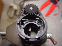
 
Here's a simple mod I did to increase the spring tension on my Magura throttle:

1. Remove the 2 little black screws on the side of the throttle body
2. Carefully disassemble throttle taking note of the position of the 2 spring latch holes (and their relation to the throttle stops)
3. Drill a 2mm hole (4.5mm depth) approx 90 degrees CW from the original hole
4. Reassemble throttle using the new latch hole

Throttle should now feel more "heavy-duty" and less prone to "accidental or runaway discharge"

:lol:

important: forgot to mention, you will need to move the pot gear (throttle body, wire side) fully CCW before reassembly and use a voltmeter to ensure the end-points fall between 0 and 5k ohm.

DSC00449.JPG
DSC00450.JPG
 
Back
Top