Dropout Failure Experiments, and a call for Fork Donations

Affliction said:
Hub motor axles appear to be very soft metal.

I would say it appears otherwise. In your case you are chasing threads with a die on an already threaded axle, of course it's not going to take much force. The hub motor axles are all heat treated, Nine Continent I know spot checks them with a Durometer (I didn't ask what the actual spec was, but will do that), and if you make a torque plate from regular cold rolled steel and spin it out, the hub motor axle will carve threads into your steel, and will itself be barely damaged. Perhaps "very soft" compared to carbide or whatever, but as far as machinable steels go they appear to be more on the harder side.

Justin
 
justin_le said:
Affliction said:
Hub motor axles appear to be very soft metal.

I would say it appears otherwise. In your case you are chasing threads with a die on an already threaded axle, of course it's not going to take much force. Justin
This is not quite true. I am not chasing pre existing threads at all but rethreading to a coarser pitch as a means of repair of stripped threads.
Chrystalite axles are threaded 12mm X 1.25 pitch, I'm simply cutting new deeper threads that pretty much eliminate the original threading.
I find 12mm X 1.5 pitch a good solution to repair stripped axle threads. I must have done a good dozen axles now on wilderness energy and Chrystalite hubs. They all seem to cut easilly with no burring. I usually have burring occur on harder bolts. ex I have to make more threads on a bolt not threaded to the head. On harder bolts I seem to get a really rough cut.
 
Affliction said:
This is not quite true. I am not chasing pre existing threads at all but rethreading to a coarser pitch as a means of repair of stripped threads.
Chrystalite axles are threaded 12mm X 1.25 pitch, I'm simply cutting new deeper threads that pretty much eliminate the original threading.
I find 12mm X 1.5 pitch a good solution to repair stripped axle threads. I must have done a good dozen axles now on wilderness energy and Chrystalite hubs. They all seem to cut easilly with no burring. I usually have burring occur on harder bolts. ex I have to make more threads on a bolt not threaded to the head. On harder bolts I seem to get a really rough cut.

Do you have a thread somewhere about re-threading the axles. I partially stripped my crystalyte 5305 hub when I first installed it. I'm using alonger bolt now so it works, but I'm keen to know how it can be repaired. Thanks.
 
patrickza said:
Do you have a thread somewhere about re-threading the axles. I partially stripped my crystalyte 5305 hub when I first installed it. I'm using alonger bolt now so it works, but I'm keen to know how it can be repaired. Thanks.
Chrystalite 5 series has a 14 mm axle. I havn't had to rethread any 14 mm axles so far and I'm not sure what the original thread pitch is either.
My best guess without seeing it is it's probably 14mm X1.5. The way thread pitch steps up you have to take into account not only the width between threads but also the depth as it's equal to the width ex. 1.5mm between threads is 1.5 mm deep into the bolt.
You need to pick a coarser thread pitch that mostly eliminates the old depth of the thread but not too coarse.
My best guess is you need to go 14mm X 2.0. Find some automotive lug nuts and recut the axle to that size.
 
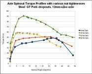
First set of results graphed here:
Nut Tightness on Spinout Torques.jpg

Tightening the nuts to 90 N-m, we were so sure it was going to strip the threads, but it didn't, and something quite non-linear happened between this and the 60 N-m test that increased the torque required to cause axle spinout by a substantial amount.

Will do a thorough description of the test procedure later.
Justin
 
Would you recommended tightening the eZee hub motors to 90Nm? I'm afraid I might strip the threads, or even crush the aluminum dropouts on my bike.

I'm curious as to what is the maximum torque a standard axle/bolt starts to strip at.
 
Its pretty simple

Your bike must have steel forks

Your ebike then must have a torque arm

Its not safe for a hub motor to be over 700 watts. Way too much torque.
 
I tend to agree about the steel dropouts. At least for installing without tourqe arms. This first graph is a no tourqe arms test.

Clearly an axle hard enough and a nut that allows tightening to 90 helps. I don't know that it would be good to squeeze alloy that hard either, but I would never run a powerfull motor on alloy drops anyway. The established safe method for installing powerfull motors to alloy frames is a custom made steel tourqe plate, that effectively replaces the alloy rear drop with a steel one.

About the 700 watts, I don't agree. But that is about the limit for running without tourqe arms.

I would say that 700 watts is about the limit you want to put on a bike and sell it, and be liable for though. :roll:
 
I'm really curious as to what point aluminum forks will snap.

I have 1100W geared on this fork right now, with a not so thick torque arm: http://www.chainreactioncycles.com/Images/Models/Full/7846.jpg

Previously i had it on the most crappy fork in the world, i would not recommend this fork to anyone as it comes with a lot of wobble right out of the box: http://northernbeachescycles.com.au/shop/images/suntour%20fork%20sf8.jpg
 
dogman said:
I tend to agree about the steel dropouts. At least for installing without tourqe arms. This first graph is a no tourqe arms test.

Clearly an axle hard enough and a nut that allows tightening to 90 helps. I don't know that it would be good to squeeze alloy that hard either, but I would never run a powerfull motor on alloy drops anyway. The established safe method for installing powerfull motors to alloy frames is a custom made steel tourqe plate, that effectively replaces the alloy rear drop with a steel one.

About the 700 watts, I don't agree. But that is about the limit for running without tourqe arms.

I would say that 700 watts is about the limit you want to put on a bike and sell it, and be liable for though. :roll:

Yeah you probably don't want to be sending one of those out the door unless you throw two torque arms on it!

I will be curious about the aluminum dropouts also...it seems like they would be slightly more common on ebike conversions since a lot of people like to do dual suspension frames.
 
This is a very informative thread for me, because I am just starting my first ebike build, using a X5303 motor with a 48v 40a controller.

I have read with great interest the thoughts and results in these pages full of information. Something keeps coming to mind, and maybe someone can comment on my thoughts.

The way I generally understand it, and keeping the situation where the axle nuts are loose out of the picture, all these shear results and metal smear results happen when there is
almost max torque (N) applied, correct?

What I keep asking myself is this: What if when I use the throttle, I start slowly, and gradually increase my speed? Then my fork dropouts will never see max N values, correct? If I am
cruising along at say 25mph, and then go to 3/4 throttle, the forks will not see as much N force as when I go from a dead stop to 3/4 throttle. Or am I wrong about that?

In other words, if I don't do burnouts, and if I don't go from a dead stop to max throttle, there is a good chance that I might never stress the dropouts to their fail point, yes?
 
Yes if you spread the torque out over a longer time period you will not be seeing a very high peak torque on the dropouts. The opposite is true as well...if you start out slow and then hit 100% throttle in an attempt to do a front wheel burnout...you may end up doing a faceplant. :roll:
 
lester12483 said:
Its pretty simple

Your bike must have steel forks

Your ebike then must have a torque arm

Its not safe for a hub motor to be over 700 watts. Way too much torque.


Not necessarily, it just has to be engineered properly. The forks are ally, the reinforcements are STEEL. And the end is closed over the axle - this is important even if I have an axle spinout I will not lose the front wheel.

I have over 10,000km, with 1300w, and mucho abuso on these forks. I've broken 2 frames, 2 rims, seatpost, rack twice, pedal...I've lost track....but the forks keep on trucking.

file.php
 
Not necessarily, it just has to be engineered properly. The forks are ally, the reinforcements are STEEL. And the end is closed over the axle - this is important even if I have an axle spinout I will not lose the front wheel.
One thing I got to give to Aussies is their ingenuity! :D Our consumerist north american society could never figure this stuff out.
I've modded my front forks and I don't use torque arms! And I'm well over 800 watts on my front hub.
Bikes just aren't designed to handle hub motors. There needs to be a new standard for E-bikes.
 
Mark wins the best tourqe arm award again. This pic gets reposted all the time.

Re Journey Guy. Yep, how you use the throttle can affect the tourqe load on the dropouts. But the single most important thing is how the nuts and washers fit into the dropouts. There is much anectdodal evidence that poor fit of the oversize motor washers and nuts into the cups of alloy front forks are responsible for many of the alloy front fork failures. When the large washer spans a space under it, the forces when the nut is tightend spread the dropouts. But should this happen, Marks design of tourqe arm would keep the motor on the forks and prevent a faceplant.

Personally, I would not run a motor on alloy front forks without something as substantial as Marks setup. Call me fraidy cat, but my broken up shoulders are just now getting fully healed from my last face plant 20 months ago. But on the rear, I would not hesitate to run an x5 on an alloy frame with good tourqe arms or toruqe plates to back it up.

Tight nuts do help, on my Fuji, I run an x5 with no tourqe arms on a steel frame. No problems so far, and I don't baby the throttle.
 
What about using multiple thinner torque arms and washers with flatted holes in between? This would multiply the friction-shear area.
 
el_walto said:
Would you recommended tightening the eZee hub motors to 90Nm? I'm afraid I might strip the threads, or even crush the aluminum dropouts on my bike.
I'm curious as to what is the maximum torque a standard axle/bolt starts to strip at.

ME TOO! I thought this would be a pretty straightforwards and easily reproducible experiment. We used an even larger wrench on the nut, and started pulling it tighter and tighter while reading the force on the load cell:
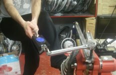
Adam reefing on wrench.jpg

The length of the wrench was 27cm. We had to lever with the foot against the vise and were pulling with upwards of 105lb when finally, fwoomp, it seemed to give. 105 pounds is a huge amount of force to put on a big wrench like this, I couldn't imagine anyone tightening a nut on a bicycle that way, and translates to 125 Newton Meters.

Turned out that it wasn't the threads that gave way, it was the actual wrench splaying open and cornering off the axle nut:

View attachment 4

We took the nut off and the threads were still perfectly in tact, save for some shavings of metal plating that came off the nut.
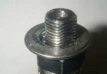
Axle Threads Seem OK.jpg

dequinox said:
Perhaps the axles Justin has are of a different alloy than the one's you work with. That might explain the stainless torque arms getting mutilated while the axle was less affected.

Yes, so all of Affliction's (Ben's) comments seem to be with regard to Crystalyte axles. Well we have some of those lying around too. So same test as above was done on a slightly used 400 series rear axle. The peak torque was 70 N-m when the nut started to spin freely. Definitely stripped threads:

View attachment 2

We then flipped the axle around to repeat the test on the other side to get a few more data points and get a sense for the repeatability. And guess what, on THIS side of the crystalyte axle, we had it all the way to 130 N-m when the wrench slipped and rounded the nut as above with the eZee axle.
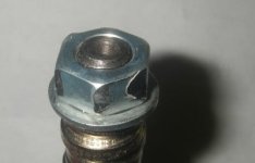
2nd Crystlayte Axle, nut rounded.jpg

So, while one end of the Crystalyte axle stripped all it's threads at 70 N-m, this side withstood 130 N-m, with the threads still almost perfectly in tact:
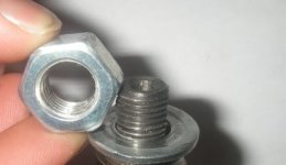
2nd Crystalyte Axle, threads OK.jpg

Not totally sure what to make of this. Either there is a huge variability in the temper on the Crystalyte axles, or more likely I think it is the mechanical tolerances on the axle threads, with one side being a looser fit in the nut and hence much more prone to stripping. In any case, we're going to need to purchase a real combination wrench set in order to properly complete these tests, as the adjustable one just isn't up for the torques involved.

Justin
 
justin_le said:
Will do a thorough description of the test procedure later. Justin

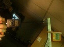
So here it is. We picked up one of these digital inclinometers from Lee Valley Tools:
http://www.leevalley.com/wood/page.aspx?c=1&p=57056&cat=1,240,41064

That was fixed to the end of the lever arm. Then we videotaped the readings of both the inclinometer and the hanging scale as we slowly pulled the lever arm down to cause the axle to spin in the dropouts. Slo-mo playback to get the data. The inclinometer readings were sometimes a bit jumpy and slow to update, but it seemed to do the trick:

Axle Spinout Test Apparatus.jpg

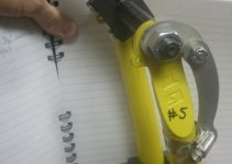
We did one more test in addition to the 4 nut tightnesses posted previously. In the 5th experiment, we had just hand-tight axle nuts but used one of the 3/16" 'universal' torque arms as well to see how much of an effect the torque arm would have.

Test#5, GT Fork with Torque Arm.jpg

The effect in this case was that the torque arm by itself boosted the axle spinout resistance quite a bit over loose nuts with no torque arm, but still not as high as the 90 N-m axle nuts.


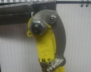
The failure mode for the torque arm was not the axle smearing in the torque plate, but the hose clamp itself slipping and sliding down the fork tube. At some point, the axle rotation would have 'bottomed out' the two pieces of the torque arm, and no further rotation would have been possible without the axle actually spinning inside the cutout of the torque plate.

Test#5, after test.jpg
 
As far as the puzzle with the clyte axle taking 70nm on one end, and holding 130nm on the other, a smear of moly-lube on the threads can make a very substantial difference in indicated torque vs the tension on the axle.

In race engine building, we only use a torque wrench on the critical fasteners you can't get a point of reference from the backside of the fastener. (which isn't much when you use studs for head and main girdle, and bolts for Rods).

We throw a special bolt-strain measuring tool with a dial indicator onto the dip in the face of the fastener, and one on the end of the fastener. Seat and zero the gage, then proceed to torque until you've set the optimal stretch indicated by the manufacture. The bolts all have a consistent modulus of elasticity and x-section, so when you set the stretch distance, you know you've accurately set the correct tension on the bolt.

When you try to estimate how hard a bolt is clamping by setting a torque value on a nut, what is really happening is the conversion of a supplied torque through a friction interference of a thread pitch, and the actual loading on the axle is determined by this friction value. This friction value can be surprisingly variable.
For example, when setting rod-bolt torque with premium no expense spared and clean fasteners, running dry clean surfaces and setting torque to 40ft-lbs could mean 0.05" stretch on the bolt (a direct representative of the tension on the fastner, aka all that matters for our needs.) To match the exact same amount of tension on the fastener on a bolt with bit of a moly torque compound on the threads, 0.05" of stretch might occur at only 25ft-lbs measured at the wrench.

It's extremely difficult to ensure no lube is in any of the threads, so we use torquing compound (Molybdenum Di-sulfide grease generally). This torquing compounds lets us know everything has a uniform friction, and most torque tables for fasteners will list a 'dry' and 'greased' torque spec for the fasteners. Depending on thread pitch and bolt size the difference can be pretty big sometimes.

This info could hopefully help to understand where some range of difference in data collected could be coming from.
For the cylte axle though, it seems like such a big difference, they probably used a hardening machine setup for doing bolts that only dip's the threaded-end in the hardening fluid after heating. They wouldn't be able to dip it on the other end without heating the whole axle up again and loosing the temper on the all ready tempered end. Just a wild-guess, might not be related at all, but it could be a factor.

I love the great work you're doing, and the excellent approach you take towards your work.

Keep up the great work Justin!

-Luke
 
justin_le said:
Not totally sure what to make of this. Either there is a huge variability in the temper on the Crystalyte axles, or more likely I think it is the mechanical tolerances on the axle threads, with one side being a looser fit in the nut and hence much more prone to stripping. In any case, we're going to need to purchase a real combination wrench set in order to properly complete these tests, as the adjustable one just isn't up for the torques involved.

Justin
UGH... LFP types faseter than me.... Dito what he said about lubrication and measuring stretch plus:

Where were the nuts sourced? Based on my own (automotive) tinkering I've learned that a 12mm nut and bolt is definately not a standard... the manufacturing tolerence for an ISO standard quality 12mm nut and bolt (read not from canadian tire's parts bin... and who knows what passes in china) allows for anywhere from 1.80mm to 1.26mm of thread engagment. Given that bolts use a 60 degree taper you can easily see why there is a great deal of variability in the torque loads they can handle since the taper further amplifies the spread in clamping material available.

Even going to a high quality fastener won't solve all of this, but it will help to get things more consistant.
 
If a person is overly-concerned with the possibility of stripping due to the mechanical tolerances...they could always throw some teflon tape in there to help cushion the threads a bit. I'd be interested to see if it helped that axle that you stripped on one end, Justin. Unfortunately you'd need a micrometer to check the "new" axle you go to test to see if in fact there was a difference in thread engagement on each end of the axle.

It may be that there is a different temper, though that's a little less likely IMO. One way to check is to grind off a section of each end of the axle so it is flat and bare...then run a file across it with one even stroke. Check the 'feel' and the depth of the cut after on each end. If you get the impression that there is a significant difference then maybe it was an uneven temper.

And hey thanks again to ya Justin for such a well-documented procedure...the data should be as good as any lab experiment for our purposes!
 
liveforphysics said:
As far as the puzzle with the clyte axle taking 70nm on one end, and holding 130nm on the other, a smear of moly-lube on the threads can make a very substantial difference in indicated torque vs the tension on the axle.
We throw a special bolt-strain measuring tool with a dial indicator onto the dip in the face of the fastener, and one on the end of the fastener. Seat and zero the gage, then proceed to torque until you've set the optimal stretch indicated by the manufacture. The bolts all have a consistent modulus of elasticity and x-section, so when you set the stretch distance, you know you've accurately set the correct tension on the bolt.

When you try to estimate how hard a bolt is clamping by setting a torque value on a nut, what is really happening is the conversion of a supplied torque through a friction interference of a thread pitch, and the actual loading on the axle is determined by this friction value. This friction value can be surprisingly variable.
For example, when setting rod-bolt torque with premium no expense spared and clean fasteners, running dry clean surfaces and setting torque to 40ft-lbs could mean 0.05" stretch on the bolt (a direct representative of the tension on the fastner, aka all that matters for our needs.) To match the exact same amount of tension on the fastener on a bolt with bit of a moly torque compound on the threads, 0.05" of stretch might occur at only 25ft-lbs measured at the wrench.
This is not entirely accurate for this situation of fastening. Torque-to-yield bolts are used when you have a long fastening bolt and the tortional rebound of the long fastener throws off the effectiveness of using a torque wrench for final tensioning.
There is friction on the nuts to axle but this has a very minimal and insignificant effect due to the very small gap the torque is being applied to.
A torque wrench is just fine and totally accurate for this testing.
I do agree tho that Chrystalite axles are improperly tempered and I have found some to be softer than others.
file.php

Why don't you try rethreading this stripped axle to 1.5 mm pitch and try the test again?
I fix these all the time by doing this :mrgreen:
 
"Surely somebody converted a suspension bike and given the advice from this list, replaced the original suspension forks with solid steel ones, and now has this extra pair of forks and a nagging question in their head about whether they would have been strong enough? Now you can find out!"

Hey, you are talking about me. I am assuming that you still are looking for suspension forks to test. In the interest of advancing the pool of knowledge I am willing to send my old suspension fork from my Kona Fire Mountain. I believe that it is a Rockshox II fork.
Do I send the fork to? :

Attn: Justin
The Renaissance Bicycle Company
4570 Main St
Vancouver, BC, Canada
V5V 3R5

,
 
While the two peice tourqe arm clearly is a design to fit more bikes, I have felt from the start that the pivot point with a bolt introduces a possible weakness.

Two bolts would prevent that rotation, but the customer would have to drill at least one of the second holes, once he sets the angle.

At the forces you are testing at though, wouldn't a lot of us be over the handlebars by then? So the current design is most likely fine, with tight nuts.

If if worries somebody, the tourqe arm could be welded once the angle was set I suppose. Then the clamp couldn't slip down the fork.
 
dogman said:
While the two peice tourqe arm clearly is a design to fit more bikes, I have felt from the start that the pivot point with a bolt introduces a possible weakness.
Two bolts would prevent that rotation, but the customer would have to drill at least one of the second holes, once he sets the angle.
The shear strength of the bolt can simply be increased by using a bolt that's better than Chinese cheese. If the torque arm is worth its mettle, it's not going to drill easily. Drill it out for a larger diameter bolt if there'd be enough metal left around the hole.
At the forces you are testing at though, wouldn't a lot of us be over the handlebars by then? So the current design is most likely fine, with tight nuts.

If if worries somebody, the tourqe arm could be welded once the angle was set I suppose. Then the clamp couldn't slip down the fork.
FWIW:
Justin road tested to destruction the stainless steel hose clamp holding a torque arm.
He runs a front hubby on the Big Dummy, He survived unhurt but missed the ride that night.
 
Back
Top