eBike Master Switch Design

All true, except the last one. The zener will protect the sensitive gate.

The switch configuration is the biggest show stopper. Something like your fast-kill modification could be done.

Isolation I don't see as a big deal below 100v. Hopefully the entire system is isolated from the frame, so you need multiple failures to have a safety problem. The frame making contact with the negative side of the battery is just as dangerous as having it touch the positive side.

An opto coupler would require some kind power on the emitter side, so not sure how you'd get around having pack voltage somewhere. Having pack voltage fed through a 1M resistor will be pretty safe.
 
am I missing something....

cant the power just flow through the diode, capacitor and resistor to the controller no matter what position the switch is? Obviously not capable of much but still live? From what I can understand you still need to reference the pack on one of the legs of the fets for them to work?

sorry for derailing your thread Alan :oops:
 
rodgah said:
am I missing something....

cant the power just flow through the diode, capacitor and resistor to the controller no matter what position the switch is? Obviously not capable of much but still live? From what I can understand you still need to reference the pack on one of the legs of the fets for them to work?

No. When the gates are grounded, once the cap charges there's no current flow with DC. There's just the leakage through the FETs then, a few microamps.
 
hi alan

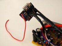
wanted to show some pictures. hope you are not too shocked that i cut your board in two :)
reason is: i want to fit it inside the controller casing and 2fets (3077 as it's 12s lipo) are enough. the controller is a 9fet installed in a 12fet case. so there is some 1.5cm free space on each end. and there will be the switch installed.

the board is cut in half and 3077s with a little heat sink that acts as a spacer as well is installed on the backside. please ignore the resistors. they are not installed finally. they are only for trying out different values.

2014-03-11%20at%2021.01.20.jpg

this will be the final place. i will install a little led to know when it's turned on

2014-03-11%20at%2021.02.14.jpg
 
good idea with the bigger controller case :)
what switch do you use?
I have a non waterproof 3-wire keyswitch from conrad elektronik because i could not find any keyswitch wich is protected against water. at this high voltage and low current requirements im afraid it will switch on or off or short circuit if some water come to the contacts..
 
i now did again some testing with a 2N3906 installed with 2x 56k resistors. due to a stupid mistake i shorted something and a trace burned the last time i tested it.
now everything is repaired, and i connected the switch to my 12s lipo and my 9fet controller with a ca-v3.
no spark when plugged in. then supply to pin2. turn on is almost instant - shorter than a second. so if you connect the battery with the switch in on position you will get a small(er) spark.
turn off time for the CA is fast enough that you can see a super short "low voltage" and the controller is off. drop from 45v to 5v in about a second, then it takes 10?s to go down to 1-2v. voltage drop is fast enough for the CA not to log this low voltage as "Vmin". so when you turn it on again it shows the "really lowest" voltage - so around the same voltage as before. i hope you understand what i mean.
with my last switch it showed some 10-20v because voltage drop was so slow that the CA couldn't say if this was regular voltage sag from the battery or a power cut.
so over all i'm very happy now. rich was so kind to send me one of the fets mention by alan in the first post but it seems they are not really needed. still i will test it to see if thing change.
so if i still could ask for a wish: i'd like to have longer turn-on time. if turn off is shorted it would be welcome but not necessary ;)
 
Glad to hear about your success, and thanks for the update

To lengthen turn on time you might try using double the value for R1/R2 or C1/2/3. Increasing C1/2/3 may increase turn-off time, whereas increasing R1/R2 should not change turn-off time. If you are using 56K now perhaps 100K each for R1/R2 would be good.

I will be testing one of these myself soon with the FET turn-off. I plan to power the CA from the KILL switch directly, so it won't see the slow rise/fall of voltage that the controller sees. This should avoid any problems with the CA reading the wrong voltage for Vmin. Other loads like lights, etc should be on the switch output and will see the rise and fall of the output voltage.
 
I changed the resistors for 100k now and it works fine. Turn on seems to be around a second. Turn off is almost instantly. Around a second from 50 to 3v. With a little DC/DC converter parallel to the controller it's super fast.
But one thing still worries me. If I disconnect the battery and after some time reconnect it, there is a small spark, the CA turn on for a fraction of a second and goes off immediately after that.
What can that be??? Feeding pin 2 with supply voltage turns the circuit on, removing it turns it off. Disconnecting the battery and reattaching it shortly after doesn't give a spark, and also no flashing CA.
 
Great progress on the turn-on and turn-off delays.

A small spark when connecting the battery is much better than a big spark. :)

We'll have to take a closer look at the value of R3 to see if we can reduce this "initial connection" surge.

If you want to try something you might try making R3 larger, say 10K, and see how that changes things.

Before the master switch is connected to the battery the C1/2/3 caps are initially discharged. When connected the switch output rises rapidly to +Battery, charging the C1/2/3 capacitors. The charge current flows through R3 and on to the FET gate bus, raising the voltage on the FET Bus. This would turn the FETs on, but Q5 comes on and attempts to clamp the main FET gate voltage bus down and keep it off. So we have a race between charging C1/2/3 and Q5 trying to hold the bus down.

Izeman is using a bipolar at Q5 rather than the designed FET, so the gain is lower that it would be with the FET.
 
so those are the parts used by me:

Code:
R1,R2 100k nominal 1/2w
R3    10K
R4+7  1K
C1-3  1uF (NonPolar) 100v - one C installed on the upper side of the board @C1
D1    12V zener
D2,3  1N4148
Q1+2  Main FETs, nominally for 75V: IRFP3077 - installed @Q1+2
Q5    2N3906

this is a perfect setup which should work easily for the 2000w setup @50v i planned.
there is no spark at all when i connect the battery, turn on time is below one second, as well as turn off. it's almost instant.
 
izeman said:
Alan B said:
At the moment these are still in development.
damnit. and i use it in production :( i'm abused as beta tester ;)
alan: i guess you can start production. they work just as needed!

Your testing is helping to move toward production. Excellent results. Are we abusing our testers? Hopefully not too badly. :)

So far none have gone up in smoke. :)

I have three more bare PC boards, three are out in the field now. I plan to use one for my Borg for some "production testing", so two are available. PM if interested in these.

Are there any more change requests? Seems we are getting close to a release.
 
I don't mind being a guinea pig. lol Just ordered a 65v 80v peak 40a breaker and just run a momentary precharge switch for now. Have a speedict and it can't be good hooking and unhooking it. That will work for now I suppose. :)
 
I had not planned to do the status LED, or forgot if I did. In my case the switch is buried in the cowlings and status won't be visible, the CA and lights being on tell me that. But I will consider it. Update - Seems to me that I had an LED at one point (between V1.0 and V1.1) but it was dropped when I was doing the Hammond box re-org due to space. One problem with an LED is it wastes power here, the supply for this board is high voltage.

There were some comments about the Hammond box wiring fit, not sure there is a solution for that. I was planning to use heatshrink or tape to enclose mine to keep it small and light, so I didn't get the box to try. The clear silicone tape seals to itself and stretches to make a conforming watertight cover, of course the wires aren't sealed.

We'll see what comments we get, and review the old ones before going forward. I'm not sure when I'll have time to mod the design, we could punch out a few more of these boards in the interim if folks want them. Should I make a small run of these?

I'm not planning to sell built up boards at this time, just bare boards or perhaps partial kits to solve the parts availability issues.
 
Some good work going on here. If I ever need a bms to handle big power, I will almost certainly buy a $15 one and increase it's power handling with this used as a relay unit.


I'm getting feelings of de jar vous. I hope I didn't post already. It has crossed my mind many times..
 
I'd defenitely be interested in your two spares...

...I'm going to do a run of 20 bikes starting in July. I'm building 2 prototypes to get my systems down before investing in large orders, and 2 to evaluate would be great.

....buy it now.
 
I'd like to keep evaluation boards to one per person (at one time) to maximize feedback and let more folks have a shot at one. Drop me a PM.

I'm considering making a small run of these. I'll look into it. That would not be limited in this way. Probably take a couple weeks to get them. I'll look into it.
 
Back
Top