You are using an out of date browser. It may not display this or other websites correctly.
You should upgrade or use an alternative browser.
You should upgrade or use an alternative browser.
Electric Chopper Project
- Thread starter ecustom
- Start date
I would make a clamp.
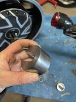
My 5kw motor started to rotate forwards and backwards with the original equipped tourque "arm" and made squicking noises.
I have made to halfs and screwed them together, so that movement is impossible.
Pics of my tourque clamps in Post #3
My 5kw motor started to rotate forwards and backwards with the original equipped tourque "arm" and made squicking noises.
I have made to halfs and screwed them together, so that movement is impossible.
Pics of my tourque clamps in Post #3
Last edited:
Agree with @dominik h , clamping would be bettewr/best. In fact, you could probably do it with your existing setup. I didn't see that you had that beefy insert, which is great. I'm wondering, would you be able to drill and tap that thick piece of metal so that a bolt can torque right down onto the axle flats? That would work, I think.
ecustom
100 mW
- Joined
- Apr 1, 2019
- Messages
- 37
Today I ran into somewhat of a problem or two. I did some 12V wiring to hook up a key switch, contactor switch with the precharge resistor relay and the contactor and nothing worked. I applied 12V over the SSR relay and didn't see the little light switch on but I suppose SSR's must have load to work? I also in my haste (since I haven't wired up a flyback diode, because I couldn't find one) applied 12V across the contactor coil but nothing happened there as well and now I noticed the clearly visible label saying that coil voltage is 96V. That complicates stuff a but I suppose I'll just add another SSR relay, and make sure I get a sufficiently rated flyback diode.
I haven't hooked up the main battery or the controller yet.
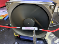
Do you suppose this power resistor will do as a capacitor precharge resistor?

I haven't hooked up the main battery or the controller yet.
Do you suppose this power resistor will do as a capacitor precharge resistor?

ecustom
100 mW
- Joined
- Apr 1, 2019
- Messages
- 37
The closest one I have in my drawers is a 270Ohm 9W, but I'll switch to that one and time how fast it precharges.1kOhm is too much. Your capacitors will charge too slow.
I would take something in the range 20-50Ohm with 10-25W
Nevermind; I found the original controller package and now have both a suitable precharge resistor and flyback diode.
Last edited:
Dui ni shuo de dui
100 kW
You are using an ANT BMS: it already does precharge.
You can configure the precharge current in the BMS settings directly. There's no real need for this resistor anymore.
You can configure the precharge current in the BMS settings directly. There's no real need for this resistor anymore.
peadar
100 W
I got an Ant bms thanks to your ninja build , I am getting rid of contactor ,precharge charge relay resistor etc. with bms it is way lighter , no wasted power, way simple and very clean wiringYou are using an ANT BMS: it already does precharge.
You can configure the precharge current in the BMS settings directly. There's no real need for this resistor anymore.
ecustom
100 mW
- Joined
- Apr 1, 2019
- Messages
- 37
How do you switch the pack on and off without a contactor?I got an Ant bms thanks to your ninja build , I am getting rid of contactor ,precharge charge relay resistor etc. with bms it is way lighter , no wasted power, way simple and very clean wiring
peadar
100 W
The bms has its own low voltage on and off button , i take notes from Dui ni shuoHow do you switch the pack on and off without a contactor?
peadar
100 W
acts like SSR with precharge , i have yet to program settings still learning,The bms has its own low voltage on and off button , i take notes from Dui ni shuo
Dui ni shuo de dui
100 kW
How do you switch the pack on and off without a contactor?
Remember that the BMS by itself is a contactor, its role is to cut off the battery from the rest of the circuit when various conditions are met.
There is a small button that comes with the BMS: press it for 6 seconds and it turns the BMS off, which shuts off the current output. Press it again for one second and the BMS will turn back ON. It will turn back on by gradually opening the mosfets (oversimplification, but that's the idea), which acts like a precharge system to limit the inrush current going to the controller capacitors. You can install this button anywhere you want so that it is convenient for you. Of course you can replace it with a better quality button as the one that's included with the BMS is usually just a very crappy little push button.
You can also use the bluetooth app to tell the BMS to switch on and off the discharge mosfets.
When you switch off the BMS with either one of these methods, as a safety measure, I suggest you leave your bikes main lights ON.
This way, if for any reason the BMS switches ON again (maybe you touched the BMS button by inadvertance, shorted the button wires while working on the harness, or for any other reason), you will immediately see that the power is back. This never happened to me but better safe than sorry.
That's how I've done it for the past 8 years.
Please note that you still need to install a fuse just in case something is very wrong with the BMS. The main fuse should ideally be installed between the battery pack and the BMS, so that if anything goes completely wrong somewhere in the circuit the fuse will blow and protect the battery from melting.
ecustom
100 mW
- Joined
- Apr 1, 2019
- Messages
- 37
I thought that this switch should be pressed once to turn the BMS on and then basically be forgotten about to let the BMS do its thing. Doing it this was would simplify things a lot though. No contactor, no precharge circuit, no 12v battery, just only click then go.Remember that the BMS by itself is a contactor, its role is to cut off the battery from the rest of the circuit when various conditions are met.
There is a small button that comes with the BMS: press it for 6 seconds and it turns the BMS off, which shuts off the current output. Press it again for one second and the BMS will turn back ON. It will turn back on by gradually opening the mosfets (oversimplification, but that's the idea), which acts like a precharge system to limit the inrush current going to the controller capacitors. You can install this button anywhere you want so that it is convenient for you. Of course you can replace it with a better quality button as the one that's included with the BMS is usually just a very crappy little push button.
You can also use the bluetooth app to tell the BMS to switch on and off the discharge mosfets.
When you switch off the BMS with either one of these methods, as a safety measure, I suggest you leave your bikes main lights ON.
This way, if for any reason the BMS switches ON again (maybe you touched the BMS button by inadvertance, shorted the button wires while working on the harness, or for any other reason), you will immediately see that the power is back. This never happened to me but better safe than sorry.
That's how I've done it for the past 8 years.
Please note that you still need to install a fuse just in case something is very wrong with the BMS. The main fuse should ideally be installed between the battery pack and the BMS, so that if anything goes completely wrong somewhere in the circuit the fuse will blow and protect the battery from melting.
Dui ni shuo de dui
100 kW
Yeah it is much easier this way.I thought that this switch should be pressed once to turn the BMS on and then basically be forgotten about to let the BMS do its thing. Doing it this was would simplify things a lot though. No contactor, no precharge circuit, no 12v battery, just only click then go.
You can also get the little screen that comes with the BMS as an option, it is pretty nice and can be integrated into your dashboard.
It shows many information, like battery voltage, current, state of charge, voltage of each cell , speed, odometer, etc.
ecustom
100 mW
- Joined
- Apr 1, 2019
- Messages
- 37
I will have two ANT BMS:s though. The old one and a new for the "other battery column" since I am building two 26s1p batteries (37Ah, 9V each). The only reasons if you are wondering is because I don't know how I should have gone about making the parallell connection and the load will be spread over two BMS:s.
Working on the battery mount now. think it will be easier to make progress if I mount the battery to the frame and figure out where to put the controller.
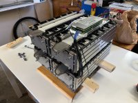
Below is 50kg of expensive goodness.

Working on the battery mount now. think it will be easier to make progress if I mount the battery to the frame and figure out where to put the controller.
Below is 50kg of expensive goodness.

peadar
100 W
maybe parallel all bms sense wires ,for 1 bms,I will have two ANT BMS:s though. The old one and a new for the "other battery column" since I am building two 26s1p batteries (37Ah, 9V each). The only reasons if you are wondering is because I don't know how I should have gone about making the parallell connection and the load will be spread over two BMS:s.
Working on the battery mount now. think it will be easier to make progress if I mount the battery to the frame and figure out where to put the controller.
Below is 50kg of expensive goodness.
View attachment 357330
ecustom
100 mW
- Joined
- Apr 1, 2019
- Messages
- 37
Wouldn't those sense-wires burn immediately when I twist the throttle for any meaningful discharge?maybe parallel all bms sense wires ,for 1 bms,
peadar
100 W
Someone else should chime in thàt has more knowledge, I am guessing,I would like to know more, the small wires do not take any main discharge current ,balance wires?
Current doesn't flow through the sense wires during discharge. A well-balanced pack should have all the cells with equal voltage. The sense wires are there for the BMS to determine (sense) voltages on all the parallel pack, and if it's a balancing BMS, to deliver small amounts of balancing current. Like 200-1000ma at most.Wouldn't those sense-wires burn immediately when I twist the throttle for any meaningful discharge?
The problem would be if you have two packs of unequal capacity, and therefore unequal power. If they're not evenly matched, one pack will deliver more current than the other, its voltage will sag a little bit more, and the cells from the pack that sags less will try to dump current into their parallel cells to equalize voltage. If the balance wires are the only point of conductivity between parallel groups, and they're too thin, they'll burn up quickly.
Take a look at this thread where we discuss a similar issue.
Dui ni shuo de dui
100 kW
Having two BMS in this case is more expenseive, but it is the proper way to go.
You can use one BMS only if the cells are physically paralleled with each other using current load capable busbars, otherwise it's just asking for trouble because if some cells arent perfectly in balance you'll have high current circulating in the tiny voltage sensing wires and that might create undesirable effects like messing up the readings or damaging the wire.
You can use one BMS only if the cells are physically paralleled with each other using current load capable busbars, otherwise it's just asking for trouble because if some cells arent perfectly in balance you'll have high current circulating in the tiny voltage sensing wires and that might create undesirable effects like messing up the readings or damaging the wire.
ecustom
100 mW
- Joined
- Apr 1, 2019
- Messages
- 37
Yeah. I will go the dual BMS route. Do I set haft the precharge current in the respective BMS or ju let one BMS do the precharge?Having two BMS in this case is more expenseive, but it is the proper way to go.
You can use one BMS only if the cells are physically paralleled with each other using current load capable busbars, otherwise it's just asking for trouble because if some cells arent perfectly in balance you'll have high current circulating in the tiny voltage sensing wires and that might create undesirable effects like messing up the readings or damaging the wire.
If I set them up identically I should be able to charge both batteries with one charger?
Dui ni shuo de dui
100 kW
Just set the normal amount, as you will switch on one BMS after the other anyway.Yeah. I will go the dual BMS route. Do I set haft the precharge current in the respective BMS or ju let one BMS do the precharge?
You'll need one switch per BMS to turn them on or off independantly.
Yes, there should be no problem with this as far as I know.If I set them up identically I should be able to charge both batteries with one charger?
ecustom
100 mW
- Joined
- Apr 1, 2019
- Messages
- 37
Realised this just as I started to think about the "new" circuit. Thanks.... as you will switch on one BMS after the other anyway. ...
Do you run the full battery voltage through a keyswitch for turning the controller on and off? If I read the Kelly diagram correctly it needs the full battery voltage att PWR. But then, how are you turning on lights? Another switch after DC-DC converter?
ecustom
100 mW
- Joined
- Apr 1, 2019
- Messages
- 37
I am using the Chinese only BMS app since my BMS is from 2019. I cannot find a setting that is obviously the precharge current. Under "BMS hardware parameters" I have a "Starting current" setting with the unit "The A" and another setting "Quiescent current consumption" with the unit "MA". Is it anyone of these?
Dui ni shuo de dui
100 kW
Yes, I have a wire coming directly from the battery positive to the key switch.Do you run the full battery voltage through a keyswitch for turning the controller on and off?
Then from the key switch I have one wire going to the controller ON/OFF wire, and another (thicker) wire going to the DCDC converter input in order to power all the other stuff.
Similar threads
- Replies
- 136
- Views
- 5,952
- Replies
- 14
- Views
- 750
- Replies
- 12
- Views
- 744


