IT ROLLS!! Got back at it today and after quite a bit of grinding the wheel/tires finally fit. All-in-all it is barely perceptible that the rear tire is narrower than it started. It will remain to be seen if the tread removal affects the handling characteristics of these tires. Here is how it currently sits:


Although i cant pedal it yet, i did push it down the road and coast a bit to see how it felt. the steering feels sluggish with the heavy wheel tire in the front. But i'll report later on how it feels at speed. I weighed the bike as it sits (still missing the freewheel, controller, rear rotor, the CA, two more batteries and some wiring ) and it comes to 75.5 lbs. In the end, i estimate it will be in the 85 lbs range. I will probably upgrade the motor at some point too so a few more lbs there. In the end i am not unhappy with the weight. if I recall GCinDCs bike came in at around 95 lbs. So, on to next steps. Still waiting on the arrival of the CA, wiring harness, freewheel (11-32) and the charger. So either work on torque arms or motor wiring upgrade. Since I don't have the materials on hand for the torque arms yet, wiring upgrade it is. Some have suggested that I wait to do the wiring upgrade. But since this motor needs to have the wire-side face plate switched out for a disc style cover anyway, I can't see opening it up twice if I don't need to. So here are the steps I followed ( for future inclusion in the motor install walk-through).
-look at the motor and decide which side you want to remove. It seems like you could open up the wire side and have access to everything (both phase and hall wires) so I recommend removing the wire side first. The following pictures show me removing the free wheel side first however because I did no think far enough ahead. Here are the two side covers side-by-side for comparison (Note the snap ring at the base of the threaded section).

I wondered about the purpose of the snap ring until I threaded on the disc adapter to a side cover without the snap ring. Turns out that the threads do not go all the way up to the face of the cover so the adapter cannot fit tight up against the face. the snap ring act as a spacer and allows you to tighten against a surface rather than just to the end of the threads (seems inherently unstable to me). So I ran out and got a snap ring for the new disc cover. Here is the disc side cover with the disc adapter threaded on:
View attachment 9
-Remove the side cover screws from the side "you want to push out of the hub" ( if you push the wire side out, you still won't have the wire side exposed since the wire side cover will still be attached to the stator). Be extra careful with these screws as you remove them as they are quite small and each has a lock washer that can easily dropped and lost (DAMHIKT).
View attachment 8
- Place the wheel on blocks so that the side you just removed the screws from is down and is high enough so that the axle has plenty of room to be pushed out from below. Arrange the wheel puller in place (these are available inexpensively at Harbor Freight). Although your wheel puller may be long enough, I don't recommend going all the way to the bottom flange. The hooked end of my wheel puller were long enough that if I went to the bottom flange they could have captured the outer edges of the side cover. Then tension on the wheel puller would cause damage. Here is the arrangement I used:

-carefully apply pressure with the wheel puller. What it happening here is that the force of the wheel puller is pushing the axle/stator/ lower side cover as one unit out the bottom of the magnet ring forcing the bottom bearing off the axle. when the bottom side cover finally released from the magnet ring it made some scary noises but everything was fine. After that i was able to screw the wheel puller by hand and push the stator out the bottom. Caution!! be extra careful with the stator once it is out of the magnet ring. the motor wiring is exposed at this point and the magnet wire has very thin insulation. minor bumps and/or scrapes and scratches can easily expose the conductors. Be ready to "catch" the stator when it releases from the invisible grip of the magnet ring.

- At this point you will have the wheel, magnet ring and one side cover still assembled and in one piece. Set them aside.
- Now provide for a safe arrangement for the stator and the remaining side cover. Use a vice or stand of some sort to prevent any of the magnet wire from coming into contact with other objects.
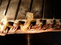
here are some shots of the inside of the motor (wrong side alas). Anyone see anything that should concern me?


There seems to be a minor spot on the outer circumference of the stator where some rubbing has occured. A close look at the hall sensors revealed that one of them has the insulation scraped off (just visible in the third picture) and possibly another one. I'll remove the other side cover tomorrow and look at the other side (where the phase wires connect) to see what may be needed. One possible problem I will run into is that the hall wires thread up through the magnet wire before reappearing at the top rim of the stator to connect to the hall sensors. All of this is then glued in place. I plan to replace these wires with teflon wire. So how to remove and then thread the teflon hal wires without damaging the insulation on the magnet wire. Any advice? I'll know more tomorrow.


") nice one.
nice one.