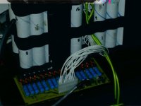
Even Newer 4 to 24-cell Battery Management System (BMS)

cycle9 said:
So, the board looks great, I want one, or several! How is the best way to order those? I tried emailing you twice at TPpacks, but no response so far.
Thanks,
Morgan

Sorry, I get a ton of emails a day, and a lot get trapped in the spam filter.

Anyway, Richard and I will test the new charge current cutoff logic this weekend, and if there are no board changes, I can make them available by about mid-week.

-- Gary
 
GGoodrum said:
The LVC portion of the circuit monitors each cell, and then trips the controller brake line if any cell dips below 2.1V. -- Gary

So how would this work if you were running more that one pack in parallel? I'm guessing that the failure of one cell would stop you dead in your tracks, rather than just shutting off the effected pack. Not necessarily a major problem as one could disconnect the bad pack and continue on your way using the remaining ones - it would just be a matter of figureing out which one caused the cutoff.
 
michaelplogue said:
So how would this work if you were running more that one pack in parallel? I'm guessing that the failure of one cell would stop you dead in your tracks, rather than just shutting off the effected pack. Not necessarily a major problem as one could disconnect the bad pack and continue on your way using the remaining ones - it would just be a matter of figureing out which one caused the cutoff.

It depends on how the paralleled packs are connected. If you connect them at the cell level, you only would need one BMS board. If your intent is to have multiple packs that don't necessarily always get connected in parallel, you would need one BMS board per pack. The LVC outputs of each board are simply connected in parallel as well, and connected to the brake switch line on the controller. Think of the LCV circuits as pushbutton switches, one for each cell (or block of cells...), all connected in parallel, and connected to the brake line. Push any one of the switches, and the brake line connection is made, which tells the controller that the brakes are being applied, so it cuts the throttle.

-- Gary
 
Any news as to when the new BMS boards will be offered for sale?
I'm down for one, the BMS that came with my lifepo pack from Cyclone in Taiwan shot sparks out a week ago when i hooked it up to go for a ride, I had only had it a couple of weeks and only used it for 20 charge/recharge cycles. It always annoyed me with its constant cut-outs.
I like this design because its simple and easy to understand and does everything it needs to, no processor, no current limiting etc.

By the way, Linear just released this battery balancer/monitor chip: LTC6802-1
http://www.linear.com/pc/productDetail.jsp?navId=H0,C1,C1003,C1037,P86662
with a eval board here: http://www.linear.com/ad/6802.jsp
but it only does 12 cells so you need a couple of them and a microcontroller/firmware to control them. Its not available yet but I figure in a year or two somone will offer a ebike product with it or a similar part inside.
 
velias said:
Any news as to when the new BMS boards will be offered for sale?
I'm down for one, the BMS that came with my lifepo pack from Cyclone in Taiwan shot sparks out a week ago when i hooked it up to go for a ride, I had only had it a couple of weeks and only used it for 20 charge/recharge cycles. It always annoyed me with its constant cut-outs.
I like this design because its simple and easy to understand and does everything it needs to, no processor, no current limiting etc.

I got tied up this weekend with family stuff, so I didn't get the new 8-channel test board completely assembled just yet. I hope to by tomorrow. In the meantime, Richard should have his going this week as well. We need to test the new charge current cutoff function before I will start offering them for sale. Hopefully, early next week.

-- Gary
 
Ah ha, nice!

I have a 24S Lipo pack that I am kluge-balancing.
Will send paypal on command for this nice solution.

Now to read back and figure out how to set LVC to 3.0V and HVC to 4.2V . . .

-methods
 
Here's a pic of my 16s5p A123 pack with the ver. 1.5 circuit.
16 cell BMS test setup.jpg

I just got the new 24 cell boards in the mail.
Some assembly required....

Keep in mind that this layout has significant changes to the previous circuit and I fully anticipate I messed up something in the design that will need fixing. As soon as I can get a few channels built, I can start testing.

 
methods said:
Ah ha, nice!

I have a 24S Lipo pack that I am kluge-balancing.
Will send paypal on command for this nice solution.

Now to read back and figure out how to set LVC to 3.0V and HVC to 4.2V . . .

-methods

Getting the LVC to 2.7v is easy since those are readily available. 3.0v ones would be a custom order at this point (minumum 1000 pcs.). There may be a sorce for these that we have not found yet. In theory, you could use a divider on the TC54 to raise the LVC, but that would add additional standby current drain and require 2 more resistors per cell. It may also be possible to put a single resistor in series with the TC54 to raise the LVC, but I have no idea if this would work reliably. I'll test this when I get a chance.

The HVC can be set anywhere by choosing a different divider resistor. We'll look into determining the exact resistor values for this in the future. I could estimate it based on present values, but the device drain throws the math off a bit, so actual testing is good.
It may also be possible to use a trim pot to make each cell adjustable.
 
That is the impression I got reading back.
LVC at 2.7V should be fine for my application. I have never discharged my pack anywhere near LVC. That would be about 65V on my pack and I have never seen below 80V.

I am really more interested in the balancing and HVC offerings of the board. I find myself charging in a more sketchy manner than discharging most of the time. I dont really trust the kelly regen to stop at 4.2V/cell so this would be a nice safety feature (even if it notifies me of a mistake by sending smoke signals). My charger is also el-sketch-o as last week the maid decided to move it to the shoe pile and managed to adjust one of the 6 voltage pots doing so :shock:

I am going to hold off on buying anymore kluge balancers and try to hop on your coat tails for a ride.
If there is an oops on the board I would be glad to buy one of those and do hay-wiring. Sounds like fun.

-Patrick
 
Glad to see you got your CARE package. :) I'm getting closer to finishing my 8-channel test board, so hopefully I'll be able to do some testing by the weekend.

Since I'm gong to make use of this 8-channel board for an 8s6p "booster" pack of a123 cells, I went ahead and cut off the unused portion of the board. With the small holes it makes it quite easy to simply use a pair of sheet metal shears, and end up with a really clean cut. I copied this technique from the guy who did that electric car conversion, where he made his own BMS boards that had individual small boards for a block of cells. He put a whole bunch of these small boards on one bigger PCB, and then cut them up. It works great. :)

Regarding the shunt cutoff voltage, the LM431 has a bit of a bias built-in, so you have to adjust the smaller resistor of the two in the voltage divider down a bit to compensate. Originally, I had calculated that we needed to use 180.0k and 84.4k values to drop a 3.65V cutoff down to the 2.5V trigger point of the LM431. Because of the bias, it ended up that by using 75.0k in place of the 84.4k values, the cutoff ends up around 3.68V.

-- Gary
 
Man I wish this forum had a Google search =) The search engine is a real bugger about short sequences and numbers.

Just to confirm, the TC54 voltage detector needs to be a TO-92 three leg package right?

I am going to go search for a 3V part.
If anyone else is looking for 3V LVC I can order a few thousand extra.

-methods

EDIT: It is the push pull type right? Not the open drain /collector?
(sorry, I could probably find that via search. . .)
 
Gary, Why don't you just add several "perforation" holes at the boundaries? Then you could just snap them off, no?
Jeff K.
 
is it possible that you should stick with the 2.7V LVC cutoff parts? if you are pulling 15A and the internal resistance is around 20 mohm, then you will have a .3V drop below the 3V resting potential, the lower limit for the lipo cells.

that way you would get the maximum from the cell and it would shut down the controller without allowing the cells to be over discharged. then common sense would help protect the battery from further discharge.

also, i want to thank gary, richard, and bob for this wonderful thread and product. your efforts are well respected and appreciated.
 
dnmun said:
is it possible that you should stick with the 2.7V LVC....

You have a good argument.
Perhaps this is more of my "old thinking" but I have it burned into my mind that the Lipo cell must not drop below 3.0V. In the past I have purchased Chinese speed controllers (for my RC stuff) with a 2.7V LVC and ended up over discharging.

I guess the counter argument would start with two situations: One where I come up on LVC at a 90A draw and another where I come up on LVC at a 1A draw.
Say I leave the headlight on overnight on my bike which runs on a DC-DC powered off the pack.
With a 2.7V LVC my light would drain the cells to 2.7V each by the end of the night.
With a 3.0V LVC I could use the BMS brake line output to open the drive signal to my main contactor (power relay)

Just a thought.

Chances are I will end up with the 2.7V like you suggest but it costs me nothing to at least try to get a 3.0V and I believe that is the better and safer solution for a Lipo chemistry. In reality I never even use more than 80% of my available AH because I dont think it is good to deep discharge them.

Thanks for sharing the idea though. I will chew that for a while to help me accept the fact that I dont want to buy 1000 3V parts =)

-methods
 
at low current draw, you could have a warning signal from the controller level or CA LVC, set at 72V plus margin. but i bet richard comes up with a better idea to allow use of the 2.7V part.
 
jeffkay said:
Gary, Why don't you just add several "perforation" holes at the boundaries? Then you could just snap them off, no?
Jeff K.

That is exactly what I did. After every four channels there are series of small holes:

24-Cell%20LiFePO4%20BMS-v2.0-PCB.png


You can break them off, but using sheet metal shears gives an even cleaner edge.

-- Gary
 
methods said:
Man I wish this forum had a Google search =) The search engine is a real bugger about short sequences and numbers.

Just to confirm, the TC54 voltage detector needs to be a TO-92 three leg package right?

I am going to go search for a 3V part.
If anyone else is looking for 3V LVC I can order a few thousand extra.

-methods

EDIT: It is the push pull type right? Not the open drain /collector?
(sorry, I could probably find that via search. . .)

For now we're sort of stuck with TO-92 packages until we can go to surface mount.
The output can be an open drain/collector, it does not need to be the push pull type.

Most of the time you would be hitting the LVC while the battery was under heavy load and the votage was sagging significantly. If the LVC is too high, you'll be hitting it way before your cells are really discharged.

If the application was something that did not have a high discharge rate, then you would want a higher cutoff voltage.
 
I am thinking that I will probably never hit LVC riding
It is much more likely that I would hit it by leaving something on overnight.

-methods
 
I hope i don't disturb the thought process here, but Methods, you can use google search for this forums. In google.com use this layout

your search site:endless-sphere.com/forums

example: motor site:endless-sphere.com/forums
 
ngocthach1130 said:
Methods, you can use google search for this forums. . .

Thank you for your thought, I appreciate the helpful hint (and sorry for this thread diversion):

** The trouble with using Google domain search is that it will only pull up pages that have been crawled and cached since the last Google pass.
It is hit and miss and unlikely to pull up 100%
With a local Google search (similar to Google desktop for your computer) it crawls only that local domain and after some period of time can return 99.9% accuracy.

An example of local Google search would be RCGroups.

Ok, back on topic =)

-methods
 
when the tests are done and you get ready to start selling the new bms kit please put me on your pm'ing list for one because i would be interested in one.
 
Richard has part of his working, but their were a few changes required (one resistor change and two additional resistors...), plu it turns out in a fit of dyslexia, I inadvertantly reversed the opto outputs when I created the bus lines for the ANY SHUNT ACTIVE and ALL SHUNTS ACTIVE signals. I did this while holding the ILD2 optocoupler data sheet in my frickin' hand. :oops: It has caused having to bend leads oround on our test boards, always a fun task.

The good news is that the new SCR-based latch circuitry, to keep the charge current FET turned off seems to work fine. I thnk Richard is still testing some extreme cases, but assuming everything still holds up, I will get new boards made early this week.

As for "kits", like I've said numerous times, I'm not doing kits this time. I will offer the boards at a bit over my cost, a set of instructions and a complete Mouser parts list. Since in order to get the costs as low as possible, I need to order lots of boards, availability won't be a problem. Mouser is not going to run out of parts and even if that did happen, we have picked the most common and least expensive parts we could. There are plenty of suitable substitutes.

-- Gary
 
GGoodrum said:
if you are not making kits then how do you explain

ew
16-Channel LiFePO4 BMS Board.
Complete kit for a 16-channel, LiFePO4-based Battery Management System (BMS). Includes a low-voltage cutoff function that can be used to activate the brake function on most controllers, whenever a cell/cell block drops below 2.1V. For charging, a high-power shunt-based circuit for each channel allows up to 1/2A of current to be bypassed, ensuring that each cell/block can reach a full 100% charge level. Individual LEDs for each channel will come on when the channel is in the bypass mode, which indicates that the cell is full. A bi-color master LED comes on red, when the charger is in the constant current mode, and turns towards green as the individual channels start going into the bypass mode. This allows standard SLA-type CC/CV chargers to be used with LiFePO4-based packs, while making sure each cell is fully charged, independent of each other.

The kit includes a two-sided PCB, with through-hole plating, individually bagged/identified parts, including a board-mounted multipin connector and matching plug (with pins) and a complete set of illustated assembly and test instructions.

A board-only option, with a parts list and instructions, is provided for those who wish to source their own parts. An option is also provided for either 250mA shunt resistors (15 ohm/2W), or the higher-power 500mA versions (6.8 ohm/5W - shown in the photo), or for both sets of resistors. Note: Use of the higher power resistors should only be used in applications where there is some room around the board, for heat dissapation.


from the http://www.tppacks.com/proddetail.asp?prod=EBKE%2DBMS%2DKit


As for "kits", like I've said numerous times, I'm not doing kits this time. I will offer the boards at a bit over my cost, a set of instructions and a complete Mouser parts list. Since in order to get the costs as low as possible, I need to order lots of boards, availability won't be a problem. Mouser is not going to run out of parts and even if that did happen, we have picked the most common and least expensive parts we could. There are plenty of suitable substitutes.

-- Gary
 
Well, if you are going to quote from my PM to you, maybe you should include the rest of my response:

That was for the last 16-channel version, which I did sell as a kit. The problem is that it took way to much time to put the kits together and I didn't make a dime on the parts, much less the hours it took my to put them together. The bottomline is that I lost my ass on those, and I won't be doing that again. Mouser doesn't charge for packaging up the parts, so this seems like a perfect solution to me. In any case, I'm very sure I'm not going to be selling kits. When I get the boards ready, I will update the site.
 
Back
Top