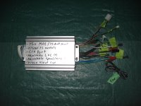
Even Newer 4 to 24-cell Battery Management System (BMS)

ebike.ca sells a "grab bag" of those connectors. Both sexes, all variations with pins and sockets.
They charge next to nothing. Come in handy.

If I were you I would just cut the connector off then twist the wires together and wrap it in like 30 turns of duct tape
Maybe dip it in "liquid electrical tape" and wrap it in shrink wrap just to be sure
I guess you could pot it in Epoxy to be extra safe.

-methods
 
Just for the heck of it

I'll post my completed board, I completed this bms in one day .. alot of time to build but awsome!

j8fhb7.jpg


Does any one know when the green light is suppose to come on? mine hasn't; I'm using my megapower 960-sr charger to charge & it gets to like .50amp charge & the cells sit at 3.69-3.70 but no green light.. any suggestions

I believe the brake works.. when i set my multimeter to the brake & ground .. there is no display on multimeter .. when the cells hit 2.1v the multimeter displays random numbers .. i guess .. it is working .. right ?

-steveo
 
Wow, one day?
You are more of a man than I am. . .

-methods
 
steveo said:
Does any one know when the green light is suppose to come on? mine hasn't; I'm using my megapower 960-sr charger to charge & it gets to like .50amp charge & the cells sit at 3.69-3.70 but no green light.. any suggestions

I believe the brake works.. when i set my multimeter to the brake & ground .. there is no display on multimeter .. when the cells hit 2.1v the multimeter displays random numbers .. i guess .. it is working .. right ?

-steveo

The green light comes on when all cell shunts are active. This will never happen with only 4 cells connected unless you cut the all shunts line.

You can test what you have by breifly jumpering the all shunts line to the ground bus. This should trigger it to go green and latch until the charger is removed. There's a picture of this posted somewhere...

Sounds like the brake is working, but your meter may not be the best way to test it. If you have a diode test function, try that. Polarity makes a difference. The best way to test is with the actual controller to make sure it really cuts off.
 
fechter said:
steveo said:
Does any one know when the green light is suppose to come on? mine hasn't; I'm using my megapower 960-sr charger to charge & it gets to like .50amp charge & the cells sit at 3.69-3.70 but no green light.. any suggestions

I believe the brake works.. when i set my multimeter to the brake & ground .. there is no display on multimeter .. when the cells hit 2.1v the multimeter displays random numbers .. i guess .. it is working .. right ?

-steveo

The green light comes on when all cell shunts are active. This will never happen with only 4 cells connected unless you cut the all shunts line.

You can test what you have by breifly jumpering the all shunts line to the ground bus. This should trigger it to go green and latch until the charger is removed. There's a picture of this posted somewhere...

Sounds like the brake is working, but your meter may not be the best way to test it. If you have a diode test function, try that. Polarity makes a difference. The best way to test is with the actual controller to make sure it really cuts off.

Hey Fechter

Could you specify what is the "all shunts line" .. I have no idea ...
I'm in the middest of deciding to either go 5p 24s or 10p 24s or 100v or 133v or 80v .. i can't decide ... gah.. once i figure out my battery configuration ...then i will build the battery harness for testing.


-steveo
 
Hi Fector and/or Gary

Can I use this BMS(4segments) to replace the BMS's of two PING 24V10AH-v1.0 batteries I have in parallel?

Thanx
Chessir
 
chessir said:
Hi Fector and/or Gary

Can I use this BMS(4segments) to replace the BMS's of two PING 24V10AH-v1.0 batteries I have in parallel?

I don't see why not. One issue is our BMS does not have any overcurrent protection, so your controller must provide that function.

If you wired all the cells in parallel (cell by cell), you could use a single BMS circuit.
 
another thing i was wondering is can the crystalyte 4840 controller detect the type of battery used?

i ask because after doing some tests i noticed the bms lvc kicks in before the controller lvc does.

the controller is around 38.4 volts and if all 16 cells of lifepo4 reach 2.1 volts it should be 33.6 volts witch is way below the controller's lvc.

i know that reading the test results and specs of lifepo4 cells there is a signal of (i think) 1000 hz ac sent through the cell to measure the internal resistance.

i was wondering if the controller does this andf if it sees a lifepo4 pack it disables or lowers the controller's lvc to a point to where permanent damage can happen as a last resort way to protect the cells should the bms lvc fails or to allow the bms to provide lvc?

i suspect that the pack is being resistance tested because the bms lvc kicked in rather than the controller's lvc.

i could tell that the bms was providing lvc because the low battery indicator came on while under load and when the lvc kicked in the cycling time was faster than that of the controller's lvc.

the controller's lvc there is a few seconds before the controller will start drawing again where the brake inhibit is immediately when released.
 
Hey everyone,

Could anyone indicate how to properly hook up the lvc with the bms?

Does this use the 5v brake?

I think i have a problem if 5v brake is needed ... my controller doesn't have a 5v brake..

i do have a mod with a 50k pot that trips the lvc in my controller though!

-steveo
 
the lvc outputs of the bms connects to the brake inhibit on the controller.

most controllers have a brake inhibit connection.

the brake inhibit is an electrical thing that disables the motor when you apply the brakes.

the reason is if you have the motor running and you apply the brakes you then are adding more load on the motor and could cause damage if it still tries to run while blocked from running.


steveo said:
Hey everyone,

Could anyone indicate how to properly hook up the lvc with the bms?

Does this use the 5v brake?

I think i have a problem if 5v brake is needed ... my controller doesn't have a 5v brake..

i do have a mod with a 50k pot that trips the lvc in my controller though!

-steveo
 
ejonesss said:
the lvc outputs of the bms connects to the brake inhibit on the controller.

most controllers have a brake inhibit connection.

the brake inhibit is an electrical thing that disables the motor when you apply the brakes.

the reason is if you have the motor running and you apply the brakes you then are adding more load on the motor and could cause damage if it still tries to run while blocked from running.


steveo said:
Hey everyone,

Could anyone indicate how to properly hook up the lvc with the bms?

Does this use the 5v brake?

I think i have a problem if 5v brake is needed ... my controller doesn't have a 5v brake..

i do have a mod with a 50k pot that trips the lvc in my controller though!

-steveo

Brake inhibit connection?

Well my controller has a purple wire on its own, is doesn't output voltage ... it seems like just a ground wire to me.

-steveo
 
i cant help much since i could not look up the 2 controllers you have but i think that may be the wire.

i hate to tell you something that may cause you to blow something so you may want to check with the manual or the place you got it before doing anything more to it.
 
L V C connection question. The E V Global controller sends a 39 volt , system voltage ,signal to the brake switches and gets 39 volts on the return pin when the brake is applied. I have the lvc leads spliced into the wires for one of the brake switches. Will the boards lvc circuit be ok with this voltage or is this a problem?
 
Icewrench said:
L V C connection question. The E V Global controller sends a 39 volt , system voltage ,signal to the brake switches and gets 39 volts on the return pin when the brake is applied. I have the lvc leads spliced into the wires for one of the brake switches. Will the boards lvc circuit be ok with this voltage or is this a problem?

Hmm... I'll have to let Richard, or one of the EEs here answer that, as I'm not sure. As for Stevo's question, what is the controller you are using? On normal Clyte-type controllers, the ebrake line simply uses a switch, or a hall sesnor, in the brake handles to pull down the ebrake signal to ground. If your controller doesn't have a such a signal, or needs a voltage to be applied to a pin to activate the brake cutout, you can usually use the throttle signal line, and let the LVC circuit pull it to ground.

-- Gary
 
Thanks Gary I have the Evg set up as well as one of Steveo`s controller`s on another bike and for us it is sounding like the throttle pull down might just be the way to go. I know Fechter has posted it around here somwhere...

2nav984.jpg

This is one of Steveo`s controllers ...all go... no stop I think he calls them a shenzen e crazy man look alike?
 
If you don't have an e-brake input, you tie the LVC connection to the throttle line to pull the throttle down to zero. from the big F on building my bms thread :D :D :D

I think I can do that :mrgreen: :mrgreen:
 
the brake inhibit is an electrical thing that disables the motor when you apply the brakes.

the reason is if you have the motor running and you apply the brakes you then are adding more load on the motor and could cause damage if it still tries to run while blocked from running.

The brake inhibit exists mainly to protect the rider. A vehicle that applies throttle without the rider's consent is out of control and dangerous. A brake fighting against the power of the motor is likely to be ineffective. There are many scenarios where the throttle can be energized inadvertently. Redundant systems to protect against this or recover from it are common.

Folks on these lists often seem to overlook such safety mechanisms. This is a very bad thing. Ebikes.ca assembles impressive electronics and kits but completely overlooks these safety mechanisms. They have removed the brake inhibit line and associated hardware from their Crystalyte kits.

Folks here suggest connecting battery LVC (low voltage cutoff) circuits across the throttle when a brake inhibit line is unavailable. This is dangerous also. Don't mess with the throttle. I've had several instances where throttle was applied without my consent on my bikes (from poorly crimped connectors from Ebikes and due to LVC via throttle.) With a powerful bike this can be very dangerous. My last such occurrence resulted in a fairly spectacular wreck.

Now I'm looking for ways to reconstitute the brake inhibit.

BTW: Electric cars tend to have multiple safety interlocks to protect from inadvertent throttle application. One example: cutoffs tend to be placed on both positive and negative power as a level of redundancy, in case one fails.
 
Icewrench said:
L V C connection question. The E V Global controller sends a 39 volt , system voltage ,signal to the brake switches and gets 39 volts on the return pin when the brake is applied. I have the lvc leads spliced into the wires for one of the brake switches. Will the boards lvc circuit be ok with this voltage or is this a problem?

The optocoupler outputs are rated for 50v, so it should be fine at 39v.

Tying into the throttle signal would work too, but you need to add a 1k resistor in series with the throttle signal line coming from the throttle.
 
rf said:
Now I'm looking for ways to reconstitute the brake inhibit.

We know where those wires go to on the circuit board, so it should be fairly easy to reconnect.

A properly implemented throttle pull down will work safely too. Bad connections can cause serious problems no matter what.

I was seriously injured by a controller failure a few years back. I had a handlebar mounted kill switch, but I was too slow to hit it. I don't do brushed motors anymore as a result of this. Proper safety features could be implemented to make this kind of thing very unlikely, but it gets complicated.
 
how does a brushed motor cause someone to get hurt?

fechter said:
rf said:
Now I'm looking for ways to reconstitute the brake inhibit.

We know where those wires go to on the circuit board, so it should be fairly easy to reconnect.

A properly implemented throttle pull down will work safely too. Bad connections can cause serious problems no matter what.

I was seriously injured by a controller failure a few years back. I had a handlebar mounted kill switch, but I was too slow to hit it. I don't do brushed motors anymore as a result of this. Proper safety features could be implemented to make this kind of thing very unlikely, but it gets complicated.
 
ejonesss said:
how does a brushed motor cause someone to get hurt?

When any one of the FETs shorts out in the controller (highly likely failure mode), you have full battery power going to the motor with no current limiting. A main disconnect relay can cutoff the controller, but it has to be fast and know when to shut off. With a powerful motor, a sudden stuck on full throttle with no current limiting will ususally put you in deep trouble very quickly.

With a brushless motor, when any one of the FETs shorts out, the motor stops and a bunch of smoke comes out. This is much safer. There are still ways to get an unwanted full throttle condition with any controller, but brushless systems are inherently safer.
 
not always ,

i have worked with brushless motors from junk copiers and laser printers and when one of the phases burn out it can cause a flat spot of sorts where you can have 1 phase not powered and can cause a jerky operation.

this can happen too if one of the 3 phase wires breaks or 1 of the 3 hall sensors stops working.

when riding you will feel the power stop and start up repeatedly.

above is if the fet opens up.

if it shorts you could have smoke like you said because you are burning up the windings but you may have locking too depending on how much power the motor has.


fechter said:
When any one of the FETs shorts out in the controller (highly likely failure mode), you have full battery power going to the motor with no current limiting. A main disconnect relay can cutoff the controller, but it has to be fast and know when to shut off. With a powerful motor, a sudden stuck on full throttle with no current limiting will ususally put you in deep trouble very quickly.

With a brushless motor, when any one of the FETs shorts out, the motor stops and a bunch of smoke comes out. This is much safer. There are still ways to get an unwanted full throttle condition with any controller, but brushless systems are inherently safer.
 
Hey Everyone!


Just wanted to ask, I have intentions of making a 40s bms board using garys bms. Do I have to modify any parts to use this bms & charge at up to 150v?
All I'm aware of is i need to connect the 6 wires to attach the additional channels.

thanks

-steveo
 
40-24=16 more wires, a small math error. why not build 2 separate BMS, one with 24 and one with 16? then with 2 chargers you could charge them both at the same time and hook them up in series again. 2 separate leads to the brake inhibit so you will still have LVC protection or i guess you can connect the LVC lines in series. where will you find a charger at 150-160 volts?

or you could build 2 separate 20 cell BMS, each identical and charge them in parallel and hook up in series, don't forget the diodes too.
 
Back
Top