Friction drive idea discussion

Solcar

10 kW
Joined
Jan 7, 2010
Messages
508
Location
Ohio River Valley
I'm glad that you mentioned the DayGlo Avenger in another thread. I didn't want to go off topic on that thread but thought you wouldn't mind me going off on a tangent here. In a similar way to how you are working with planetary gearing, I'm wondering if a viable way to do friction drive will be to do some extra speed reduction so that a larger drive wheel can be used to engage the tire.

I have been thinking that because the assembly will not only be spinning faster and be doing it more often, to keep it quieter, belts are a good way to consider. I am still experimenting with friction drive because that leverage bonus available at the wheel periphery is very attractive.

edit: replaced "torque" with "leverage" in above sentence.
 
Solcar said:
I'm glad that you mentioned the DayGlo Avenger in another thread. I didn't want to go off topic on that thread but thought you wouldn't mind me going off on a tangent here. In a similar way to how you are working with planetary gearing, I'm wondering if a viable way to do friction drive will be to do some extra speed reduction so that a larger drive wheel can be used to engage the tire.
You can use any size drive wheel you want, as long as it's outer diameter is spinning the speed you want to go--that is how fast it'll be pushing against the road (via the tire). Mostly people use really small drive wheels or rollers, so they can more directly use the motor RPM.

But using a reduction first may help the motor out, and let you use a higher-kV motor. That's why I want to use the Currie (Matex) planetary on the motor, before going to the drive roller (probably a rollerskate or skateboard wheel as before, since it's almost always dry here). THe motor I'm intending to use was made for 12V to drive a radiator fan, so it's already high RPMs. Using it at 36V put it thru hell, because it had so much of a load on it trying to spin up the wheel to the fan speed, which of course it cant' do, so it never reaches the BEMF region that limits the current flow thru the motor.

Using the planetary reduction, it'll get 4x closer to that than before. Using two in series it'll be 16x closer, and probably about right. :)


I have been thinking that because the assembly will not only be spinning faster and be doing it more often, to keep it quieter, belts are a good way to consider. I am still experimenting with friction drive because that leverage bonus available at the wheel periphery is very attractive.
Friction drive has at least one advantage, in that it's mechanically tolerant of many faults that chain, gear, or belt drive is not. It generally doesnt' work as well in the wet as the others, though that depends heavily on what kind of surface the drive roller and wheel contact area have.
 
amberwolf said:
You can use any size drive wheel you want, as long as it's outer diameter is spinning the speed you want to go--that is how fast it'll be pushing against the road (via the tire). Mostly people use really small drive wheels or rollers, so they can more directly use the motor RPM.

I think of a 1/4 inch diameter wheel trying to grip the tire and the rotational resistance that would have on the wheel. :wink: But I will still need a drive wheel with a smaller diameter than I would want even if I add down-gearing. I am considering placing the unit at the rear end below the luggage rack. That gets it out of the range of foot rotation while pedaling. However, light weight is more important there. But I want light weight anyway. Back there also gets it downwind of stuff being flung from the wheel by the roller. Plus, the rack can maybe have a fender-like shield under it.

But using a reduction first may help the motor out, and let you use a higher-kV motor. That's why I want to use the Currie (Matex) planetary on the motor, before going to the drive roller (probably a rollerskate or skateboard wheel as before, since it's almost always dry here). THe motor I'm intending to use was made for 12V to drive a radiator fan, so it's already high RPMs. Using it at 36V put it thru hell, because it had so much of a load on it trying to spin up the wheel to the fan speed, which of course it cant' do, so it never reaches the BEMF region that limits the current flow thru the motor.

I use a high KV motor too. I'm of the opinion that it will end up more resource friendly and cheaper to find ways to gear down smaller sized motors than manufacturers adopting an approach like constructing a wheel that is basically a 26" outrunner motor. I seem to recall pictures of the result of the attempt, though.

Using the planetary reduction, it'll get 4x closer to that than before. Using two in series it'll be 16x closer, and probably about right. :)

Wow I've considered two of those in series when evaluating various options, but I wonder how much noise it would make. :)


Friction drive has at least one advantage, in that it's mechanically tolerant of many faults that chain, gear, or belt drive is not. It generally doesnt' work as well in the wet as the others, though that depends heavily on what kind of surface the drive roller and wheel contact area have.

It's conceptually simple, too. :)

I think water partly accounts for why grip tape and belt sanding cloth have been used a lot recently. Plus, the former is easy to apply, even if its longevity has proven to be less than the belt sander material.
 
I just searched for skateboard wheel, and this is where I got, so excuse me for not reading everything.

How was your experience with the skateboard wheel as a friction drive roller? I want to use it as well, though, how is the performance when the road is wet in comparison with a smoot steel roller, like the can of an outrunner?

Thanks!
 
On my DayGlo Avenger, smooth skate (not skateboard) wheel rollers were very slippery when wet, and didn't work very well. Since it's dry in Phoenix almost all of the time, that's not a problem. :) Skateboard wheels generally have better grip than the skate wheels, from the types I have seen, and if I had used those I would have probably had slightly better results.

Regardless of type, since they are still a smooth surface, when used with a fairly smooth tire surface they will still allow water to evenly cover the surface between them (albeit in an extremely thin layer), causing slippage. Almost any kind of "tread" between the two to allow the liquid to be squeezed out of contact patch points would help this; the smaller and taller the contact patch points are vs the "runoff" tread areas, the better this will work, which is one reason why large-grit sandpaper can help.

Sometimes slicing up the surface of the roller in a "knurl" pattern will also help, so there are grooves for water to be pushed thru.
 
I've been working on some designs for a friction drive system that utilize a belt to reduce the pulley speed. One of my "better" ideas uses two drive rollers for more surface area and a single timing belt. My planned reduction was a 2:1 using 2 or 2 1/2 inch drive rollers and a 250kv motor. My thought is that it should give sufficient torque and grip for a full suspension mountain bike. If I want even more of a creeper gear I could run another motor through the first on another 2:1 reduction for a total of 4:1 on the second motor. You would have to have a clutch bearing between the two motors to keep motor 2 from running at double the speed and wasting efficiency while motor 1 was running in its top speed.

Another idea and design I've been toying with is a 2 speed reverse timing belt system but it is complicated as hell for me to wrap my head around and the amount of clutch bearings needed not to mention having two input shafts on the friction drive wheel(s). If anyone wants me to explain more just let me know. I've got some rough drawings on my laptop but they are kind of hard to follow the two different belt lines.

As far the friction drive wheel, I've been thinking about some of the spray on/roll on truck bed liners on the market. From what I've seen and experienced they are tough as hell and provide sufficient grip even when wet. Rhino lining which is a polyurethane spray on coating is one option or the more DIY option is Herculiner which is a polyurethane roll on/brush on coating with rubber chunks in it that give great grip. Best part is once you wear down, just roll on another couple of coats.

Carl
 
One thing I relatively recently briefly considered with my pancake motors on DayGlo Avenger's old friction drive was using two planetary gear reductions in series on one of the motors, and only one on the other, with a rocker pivot betwheen the mounts for the two.

One motor would be engaged for lower speeds, and the other for higher; I'd just use a 3-position gear shifter for this. Gear one makes low-geared dual-planetary engage, gear two disengages both, and gear three engages high-geared single-planetary.

But neither of these motors is very high-powered by themsleves, although the pair worked very well together. I never tried them with the planetary reductions, that is a later idea I hope to attempt someday. I have all the parts, I think, just not the time. (well, I could use another pair of the planetaries, as I only have two right now; they're the Matex ones used in the Currie drives; I also wish I had the couplers by Matex for putting two in series).
 
Amberwolf, I really like the idea of using planetary gear sets for different gears. They are such a compact package and can give you some great gear reduction and decent efficiency. The only problem that I see with them is their cost. I've been looking for different products that use planetary gear reductions, in hopes I could pick them up cheap and then steal the gearbox out of them. I've had my eye on the dewalt 3 out of the cordless hammer drill, but it says up to 750w and we all want more. The 3 speed bicycle hubs are nice but I don't think they have enough range of gearing. I'm still on the lookout for a deal on planetary gears that they made a lot of and are cheap.

Carl
 
Besides the simplicity, and cheapness, I think the friction drive has one more great potentiality.
The pairing of 2 different diameter rollers, running at the same speed would make for a simplistic 2 speed eBike, through the application of a simple "rocker" assembly.
 
Powdersummit said:
I'm still on the lookout for a deal on planetary gears that they made a lot of and are cheap.
All Electronics may still have the 4:1-ish Currie/Matex planetaries for $10. They are very small, and though they aren't intended for really high-power, if you don't shock-load them, they should last a long while. If you built an enclosure for them to keep out dirt and allow an oil bath, they'd probably last even longer. Matex has all the parts needed to connect them in series, or to various kinds of motor shafts, too.

But using different planetary sets for different gears is probably not that easy to setup. Rather than that, you might consider using old Sturmey Archer 3-speed hubs, as you could drive the chain input on it from the motor, and then put your friction coating on the hub itself, and drive the wheel with the hub's casing. If not shock-loading them, they ought to handle about any power that you can apply wihtout breaking traction between the roller and the tire anyway, as opposed to the failures that seem to commonly happen at <1000w when directly chain-driving them as wheel-hubs, from motors with high torque. And they already *have* an oil bath and sealed environment. ;)


Or as DrkAngel said, two rollers with a rocker or other physical shifter between them.

A wedge or stepped roller has also been suggested (and tried, I think), that shifts by moving side to side.
 
I've been thinking about the way phonographs used rubber idler drive and have been wondering about reversing the locations of the rubber in the setup. The motor would have a friction wheel, and that would drive a pulley with a rubber tire around its circumference. I see the possibility of high reduction like worm drive, but with lower transmission losses.

http://www.amazon.com/dp/B004AK7LYO/ref=asc_df_B004AK7LYO1583112?smid=A2KDF402UD3HTO&tag=pgmp-1587-95-20&linkCode=asn&creative=395105&creativeASIN=B004AK7LYO

The wheel like the one pictured in the AMC Parts Store photo might have a circumference of 6 inches and be driven by a 1/2 inch friction roller on the motor shaft. Not for high power, but it could allow for pretty low weight, and make little noise.
 
DrkAngel said:
Besides the simplicity, and cheapness, I think the friction drive has one more great potentiality.
The pairing of 2 different diameter rollers, running at the same speed would make for a simplistic 2 speed eBike, through the application of a simple "rocker" assembly.
If placed "inline", with the motor in the center, damaging bearing wear, on the motor, could be eliminated.
Roller bearings should be much more durable, and easier-cheaper, to replace.
 
I've got a real grunty planetary gearbox, out of an old winch for hauling boats up onto a trailer. It's a 100:1 reduction, which should be just about enough if not slightly too much, and I'm currently trying my hardest to build it into a baby-trailer drive. I reckon it's very strong, but I would raise the wee issue-ette of high volume levels. It's noisy in an upsetting way. Plenty tough though. Oh, and I got it for free which is always a big bonus. The cable bobbin had got a bit corrody where seawater had had its way with the animalium, but the gearbox is still in tip top condition. I think new you can buy them for quite cheap as well, but even though I've had a good look, I haven't actually found anyone selling the gearboxes on their own without the heavy duty low tech motor that normally drives it.


E
 
At that reduction of about 100:1, I would consider placing it in a setup that drives a pedal chain. Something on the order of about 20 - 50:1 is better for driving a single-purpose wheel sprocket, while I'd say about 2 - 5:1 could be good motor speed reduction when driving a friction drive roller. It depends on the motor characteristcs, however, with a smaller, lower torque, higher speed motor requiring more speed reducing gearing.
 
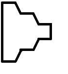
I thought of a possible 3 speed friction drive roller. I might even consider a forth, largest diameter position that wouldn't be for drive but would be for simulated freewheeling. That would give the wheel more mechanical advantage against the roller for when no assist is desired, and when the rider wants to minimize drive assembly drag.
 

Attachments

  • Proposed 3-Speed Friction Roller.jpg
    Proposed 3-Speed Friction Roller.jpg
    1.8 KB · Views: 3,875
Solcar said:
I thought of a possible 3 speed friction drive roller. I might even consider a forth, largest diameter position that wouldn't be for drive but would be for simulated freewheeling. That would give the wheel more mechanical advantage against the roller for when no assist is desired, and when the rider wants to minimize drive assembly drag.

Why bother with "simulated freewheeling" ? ... most of the newer generation of Friction drives on here have either some auto mechanism for completely removing the roller from the tyre, or a built in one way clutch bearing to minimize drive resistance.
There are several other earlier threads that covered all this,.. and conical rolls , spherical rolls, dual rollers etc etc.
 
Hillhater, I agree with the sentiment of trying to eliminate anything that can be and have the it work well. The simulated freewheel idea was based on how I have noticed that a brushed motor will turn most freely when a reverse current blocking diode is in series with its power supply. The diode prevents the motor from acting as a generator by keeping current from flowing from the motor back into the electrical system. A switch would do the same thing if it disconnected the motor electrically.

So, the idea was based on the drive roller being able to be moved over to a last and large diameter position that slows the motor down as much as possible to minimize its resistance to rotating. If a series diode or switch is also included in the electrical circuit, the need for either the freewheel or keeping the drive assembly off of the tire may be done away with.

Then, the drive assembly has only to be moved in two directions, that is, just left and right for different drive speed/torque selection, instead left to right *and in and out from the tire. That allows for greatly simplified mechanics.

My experience with freewheels hasn't been really great since I tried a freewheel out by pressing it against the tire and it did not do very well. The pressure against the tire along with the high RPM seemed to be too much for it and it wouldn't freewheel. That was a one-way roller bearing type freewheel, which I believe is also called a sprague clutch. I'm not sure about the ratcheting-type freewheel like the type used on wheel hubs, but I suspect that I would find it to be heavy and noisy.
 
Solcar said:
So, the idea was based on the drive roller being able to be moved over to a last and large diameter position that slows the motor down as much as possible to minimize its resistance to rotating. .......
.....Then, the drive assembly has only to be moved in two directions, that is, just left and right for different drive speed/torque selection, instead left to right *and in and out from the tire. That allows for greatly simplified mechanics. .

But if you have different roller dia's, then the motor will have to move "in and out" anyway .. to allow for the dia changes ?
If you read EVTodds, Adrians, or Keplers build threads , you will realise that the "in-out" movement is simple and automatically disconnects the drive from the tyre when power is shut off.
 
Hillhater said:
But if you have different roller dia's, then the motor will have to move "in and out" anyway .. to allow for the dia changes ?
If you read EVTodds, Adrians, or Keplers build threads , you will realise that the "in-out" movement is simple and automatically disconnects the drive from the tyre when power is shut off.

Indeed, it moves to and from the tire. Yet what I mean is manually moving it to and from (in and out) would not be necessary, like with the outrunner motor systems that you mentioned (At least one of EVTodd's versions remains engaged on the tire and includes a freewheel.). Manual control by the user would only be needed to make the drive assembly move side-to-side to access a wider or narrower portion of the drive wheel.

The tapered transitions between the different diameters on the drive wheel allows it to work its way to a higher level as sideways force is applied. So, some considerable force is only necessary to get it to move to a lower torque/higher speed setting (higher level, that is, wider, on the drive roller). Going the other way, it will just drop down more freely to the smaller diameter position.

Most likely, the drive roller is on its own axle and is driven by a belt.
 
EVTodds has both a roller clutch and a slide system to automatically remove the roller from the tyre when not in use.
Keplers and Adrians are pivoted to ( deliberately) to both eliminate any drag when not in use and simplify the designs so as not to need a free wheel , clutch, or any of the electrical mods you are suggesting.
Neither of them require any "manual" input to engage or disengage the drive. There is an elegant yet effective simplicity to their designs.
You have to incorporate the "in - out" motion in your design, so why not use it to disengauge the drive when not needed, and avoid the electrical complications and any hint of residual drag. ?
 
Just to clarify how my drive works a bit. My roller actually stays on the tire when the motor isn't in use. It's just barely on the tire but that's why I'm using a one way bearing.

Another side note... From what I've read about one way roller bearings you have to allow some radial play in the roller for them to work correctly. The EV Warror roller I use has bushings next to the one way bearing that are of a slightly larger inner diameter to allow for some radial movement so the bearing can lock up correctly. I've read some better explanations by some of the r/c guys. Here's one I found:

http://rc.runryder.com/helicopter/t55473p1/?highlight=freya

If you scroll down and see where he talks about the Raptor one way bearing with it's somewhat larger bushings on the side you'll understand exactly how the ev warrior roller is made.

I suspect the people on here that have had problems are simply making a roller that can't float correctly. My current roller has around 3000 hard miles on it with the original one way bearing, so they can and do work.

As far as the other pivoting drives being more simplistic well, I agree and disagree at the same time. If you want a very very low power setup then yes. If you want any kind of usable power then no. These simple designs are getting more complicated by the day. Just read all the threads about custom electronics and servos to engage the roller and prevent choppy engagement.

Don't get me wrong, there's some cool stuff being invented on here but I like simple simple simple.

I also think the multi-diameter roller is a neat idea but why not just use a small roller and a higher kv motor? Wouldn't that accomplish the same thing with less stress on the motor?
 
EVTodd said:
As far as the other pivoting drives being more simplistic well, I agree and disagree at the same time. If you want a very very low power setup then yes. If you want any kind of usable power then no. These simple designs are getting more complicated by the day. Just read all the threads about custom electronics and servos to engage the roller and prevent choppy engagement.

Don't get me wrong, there's some cool stuff being invented on here but I like simple simple simple.

What do you consider "very very low". I am happily running my design up around 2kw. No issues. Both sliding & pivoting drive designs are capable of engaging more than enough for the sort of power levels we are running.

As for custom electronics ... well the only thing I added apart from a modified servotester to accept a normal ebike throttle, was to buy this and plug it in between servo tester and ESC. The only reason I am pursueing more custom electronics is to add extra "bells and whistles" features and to try and reign in the power to make it legal. I don't know why Kepler has gone down the path of servo engagement, I haven't found any need for it.

The only advantage I think the pivoting drives have over the sliding/oneway-bearing designs is that they totally disengage from the tire. So no additional rolling resistance when not in use, or concern about out of round tires. But with a very light engagement on a nicely round tire, the difference would be slight and not a concern for those that use the assist 100% of the time.

- Adrian
 
Hillhater said:
EVTodds has both a roller clutch and a slide system to automatically remove the roller from the tyre when not in use.
Keplers and Adrians are pivoted to ( deliberately) to both eliminate any drag when not in use and simplify the designs so as not to need a free wheel , clutch, or any of the electrical mods you are suggesting.
Neither of them require any "manual" input to engage or disengage the drive. There is an elegant yet effective simplicity to their designs.
You have to incorporate the "in - out" motion in your design, so why not use it to disengauge the drive when not needed, and avoid the electrical complications and any hint of residual drag. ?

I see advantages to the systems that automatically engage the tire, yet I'm not sure I will be able implement that approach.

I was contemplating the feasibility of moving the assembly just side to side. It should also be doable to have a user control to move it to and from the tire, and there may be certain advantages to be able to carry out both types of movements by hand. A disadvantage might that if the wheel is spinning fast and the drive roller is lowered onto it, considerable scuffing might occur.
 
EVTodd said:
Just to clarify how my drive works a bit. My roller actually stays on the tire when the motor isn't in use. It's just barely on the tire but that's why I'm using a one way bearing.

Another side note... From what I've read about one way roller bearings you have to allow some radial play in the roller for them to work correctly. The EV Warror roller I use has bushings next to the one way bearing that are of a slightly larger inner diameter to allow for some radial movement so the bearing can lock up correctly. I've read some better explanations by some of the r/c guys. Here's one I found:

http://rc.runryder.com/helicopter/t55473p1/?highlight=freya

If you scroll down and see where he talks about the Raptor one way bearing with it's somewhat larger bushings on the side you'll understand exactly how the ev warrior roller is made.

I suspect the people on here that have had problems are simply making a roller that can't float correctly. My current roller has around 3000 hard miles on it with the original one way bearing, so they can and do work.

As far as the other pivoting drives being more simplistic well, I agree and disagree at the same time. If you want a very very low power setup then yes. If you want any kind of usable power then no. These simple designs are getting more complicated by the day. Just read all the threads about custom electronics and servos to engage the roller and prevent choppy engagement.

Don't get me wrong, there's some cool stuff being invented on here but I like simple simple simple.


That explanation seems to cover the case of the bearing not freewheeling. It seems to rotate on a simple shaft with washers at each end. I suspect that it might be OK to be built that way under certain conditions like low pressure or RPMs.

I also think the multi-diameter roller is a neat idea but why not just use a small roller and a higher kv motor? Wouldn't that accomplish the same thing with less stress on the motor?

Thanks. I'm contemplating the idea of the multi-diameter roller to help a small motor stay in its maximum power/efficiency zone. I hope to get more low speed grunt while retaining higher speed capability on the flats.
 
Back
Top