Friction drive idea discussion

I appreciate that encouragement! I will exert more thought into the design and try to come up with something mechanically simple enough that I can build in the relatively crude style that things usually happen here. The concept looks really enticing to me right now, considering that I don't usually get excited by very much these days. :)
 
adrian_sm said:
I don't know why Kepler has gone down the path of servo engagement, I haven't found any need for it.

- Adrian

I think a few people would be wondering the same. I mean why add more complication when the whole concept is about being as simple as possible? The actual reason is quite simple and highlights the differentiation between our systems.
The CB system (which I really like), has a stable attachment point that doesn't flex under the load of someone sitting on the seat. Gravity is also on it's side and as such naturally holds the motor away from the tire. This being said, it still relies on careful set up using a spring counter balance and a nice true running tire so that the motor doesn't scrap the tyre when not being used.

The K system is mounted to the seat post and as such can be effected by the natural flex of the seat post tube. Also the mounting location does not have gravity on it's side and as such needs a spring to keep the motor on the park stopper. To add to the complexity, having the drive mounted at a higher point on the tyre lends itself to a more critical set up and a greater chance of the drive scraping the tire.

So why put up with this apparent disadvantage in design? The reason is that I want to stay with a design that fits the maximum number of bikes. I also want it to be a complete package that holds the ESC, interface and battery if wanted. Adding a servo is something that I resisted for a long time but at the end of the day it ended up being cheap and simple addition to the drive that solved a major issue. :) The interface now has the extra servo plug and software logic. Use it or don't use it. The option is there :)
 
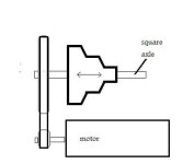
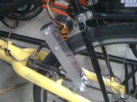
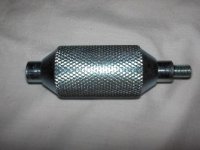
I set up a test of an assembly that would be like one in a multispeed friction drive. However, it only had one speed since I'm not a talented fabricator. It showed promise, though it was a bit flimsy to hold up to a lot of adjustment attempts. Instead of restrengthening it and continuing to work with it, I have decided to concentrate on moving the concept forward with some new ideas.

I looked into the possibility of a freewheeling roller assembly based around something like a standard single sprocket freewheel with a #25 sprocket or belt cog pulley piggy-backed onto it. Such a standard-type hub freewheel is really overly heavy duty for friction drive application since it is designed to handle forces at a 26:1 mechanical disadvantage over what is needed to drive the wheel at the periphery (26 inch wheel). That makes it too noisy at high rpms produced at the tire, and its rolling resistance is excessive on account of the stiff paw engagement. That second drawback might not really matter much in reality, though.

Since the rotation rate is higher by a factor of 26 while the torque is lower by the same factor, the material of the assembly need not be metal (except maybe aluminum), but rather, plastic should work well. That gives a big weight reduction bonus, plus it's much easier to machine. The roller's contact area with the tire is covered with grip tape or other protective material, so it doesn't matter that much that it is plastic.

The freewheel being at the roller is better than on the motor since then the motor and chain can be still if the system isn't being powered. This aspect is important at the high speed at the wheel periphery. On the test version I recently tried out, the plastic chain always turned so long as the roller was engaged with the tire, so it was not the recommended way to do it.

The freewheel would be able to slide on splines on the plastic multispeed roller so that when the roller is forced left or right, the motor and drive belt (or plastic chain) can retain a single position. If dirt might be a problem, the plastic freewheel/roller assembly might still be a good choice even for a single speed rendition of the concept. Then, the assembly would be simpler and narrower, without spline tracks and a sled-axle to get dirty or jammed.

I see really big potential for friction drive, based on the recent test I did as well as all the swell projects that fellow ES members have done.

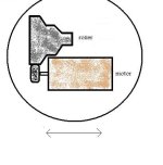
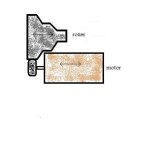
Edit: I forgot about an important consideration with shifting gearing on a multispeed assembly. When the drive wheel is moved left or right to change the drive ratio, the motor would have to move closer or farther from the drive wheel as the axis of the roller shifts in or out a little. However, if the in and out movement of the roller is around an axis that aligns with the motor axis, the belt or chain length will not want to increase or decrease, the distance between the pulley or sprocket centers will remain relatively constant.
 
Solcar said:
The freewheel would be able to slide on splines on the plastic multispeed roller so that when the roller is forced left or right, the motor and drive belt (or plastic chain) can retain a single position. If dirt might be a problem, the plastic freewheel/roller assembly might still be a good choice even for a single speed rendition of the concept. Then, the assembly would be simpler and narrower, without spline tracks and a sled-axle to get dirty or jammed.

Lately it occurred to me that the spline might better be placed under the multidiameter roller so that the roller drive assembly is kept in one spot laterally while the roller can be slid left or right on the splined shaft. Instead of an asterisk-shaped spline, maybe a simpler square will even work. I'm considering trying using a piece of square aluminum stock.

Edit: I'm also considering another way (2nd diagram)) which positions the motor in a fixed position with regard to the roller. This would enable the roller to use a rubber wheel that presses against the widest step diameter of the roller and remain there as the motor and roller are slid left or right together to access the different speed reduction levels. Since the motor propels the highest diameter spot, moving the roller to access a smaller diameter portion of the roller increases the mechanical advantage of the motor. If the motor drives the wheel at a 4" diameter spot and the roller is contacting the tire at a 1" diameter spot, the mechanical gain is 4 and the speed is 1/4. With this way, the shaft the roller is on needn't be anything special since the motor is driving the roller directly.

A third possibility also has the motor directly drive the roller on its surface rather than from the shaft upon which it slides. But with it, the motor can slide independently from the roller, giving a much wider range of gearing. An advantage of either way is that belts and pulleys aren't used.
 

Attachments

  • 3-Speed Friction Assy Idea..jpg
    3-Speed Friction Assy Idea..jpg
    7.2 KB · Views: 1,852
  • CVT2.jpg
    CVT2.jpg
    18.5 KB · Views: 1,814
  • CVT3.jpg
    CVT3.jpg
    13.7 KB · Views: 1,813
As far as friction-drive ideas go, I liked EVTodds idea so much, I made one for myself (still happy with it). There is definitely merit to the motor-shell drives like Kepler/Adrian, as they are as light and small as a drive can get.

There have been two ideas I havent seen made yet, and I felt they were worth trying. Storm suggested a cone-shaped roller and posted the pic below. The other idea was a small 50mm motor shell drive for top speed (roughly equal to a 2-inch roller), but because of the amp-heat from accelerating and also tackling long hills, an HTD belt would connect the motor-shaft to a one-inch roller as the first gear, both mounted on a rocker-arm. One inch roller is first gear, two-inch motor-shell is second gear...

conerollerSmall.jpg
 
Picture 040 (Custom).jpgI was told to keep it simple :)

Coming up on 800 miles... Not running friction tape, and no noticeable extra tire wear..

Spinner !! Same 280KV motor going strong
 

Attachments

  • my pictures 008 (Small) (Custom).jpg
    my pictures 008 (Small) (Custom).jpg
    39.9 KB · Views: 2,030
spinningmagnets said:

^That looks like it would scrub against the tire since the left part would be rotating faster than the right part due to the different diameters. It might work, but you would likely have to limit your engagement to a narrow contact patch on the tire.
 
Bill! Glad you posted again. Good to hear your drive is still running well.

Theories are fun to discuss and try out, but real-world examples are the true test
 
A variety of Drive Rollers 7/8" to 1 1/2", for friction drive builds. Staton Inc.
They also have a large variety of build components!
For eBikes, gasbikes and more!
Kits, builds components ... I bookmarked, as a valuable resource!
 

Attachments

  • 1.5 roller.jpg
    1.5 roller.jpg
    70.5 KB · Views: 2,011
http://endless-sphere.com/forums/download/file.php?id=79957

I am new to the E-Bike universe so this may sound like a stupid question but I'll take my chances
How are you going to get that to "change gears"? per say because they are not really gears

Good Idea though!

Karl
 
For the same motor rpm, the velocity that the surface of the roller travels at, increases. This directly changes the road speed.

Another way to think about it is the ratio of diameters between roller and wheel it drives.
 
Adrian, I think he might be asking how the physical process of getting to another diameter part of the roller is done.
In that case:

Hi Karl, welcome to Endless Sphere and the world of ebikes.

It's a good question you ask, if I understand it right. In the picture of the multi-diameter roller idea in which the roller slides on a square shaft, a rod containing a bearing could touch the spinning roller on each side. Each rod would be able to push the roller to cause it to slide over, one rod to the left, the other rod to the right.

Thanks!
 
my pictures (Custom) (3).jpgHey guys ... As long as we are throwing out ideas .. How about this ... A snowmobile primary clutch running on the sides of the tire like a belt would normally... mounted on a slide mount like EV Todds , but spring loaded to the tire , so it can move in and out as the revs very ... (Google snowmobile clutch) If you don't know how the clutch works.. Just a thought.. :roll: Guess I need rest ... Bill
 
You'd need a different shape to the sheaves, though, or else you're mostly going to be driving the edges of the tread or even the sidewalls fo the tire, and unless you have lots of tread thickness or wall thickness in those areas, it's gonna wear the tire out quicker than it should.

It's worse if a lot of the sheave surface makes contact with the tire, because it is going to rotate at different speeds at different contact points, as will the tire, and wear both in ways it shouldn't.
 
SOLCAR and
Amberwolf ...You are probably right ...But If I had all the parts just laying around I would have to give it a try just to see if it would work ... I think the Sheaves would work with the right tire tread design ...a wider squared off tread so there is more rubber where the TWO contact patches run on the sides... My big concern would be the weight.. And those clutches have been known to hurt people... Don't ask how I know.. Thanks for taking a look...

TO SOLCAR I just realized this thread wasn't to discuss all DIFFERENT ways to friction drive.. I'm sorry for getting off of your drive Idea ... I like your drive very much... Maybe a starter solenoid would do the shifting some how ... Bill
 
rearengine said:
I was told to keep it simple :)

Coming up on 800 miles... Not running friction tape, and no noticeable extra tire wear..

Spinner !! Same 280KV motor going strong

Am I to understand from the photos that you're using the outrunner housing as your spinner? Even if the knurled edge isn't necessary, I just have to think the motor is endanger of just one bad flex.
 
Rearengine,

Thanks.
Yet I think your contribution and other people's ideas are cool. I'm of the opinion that two heads (or many) are better than one. I appreciate the various ideas even though I'd pretty much be overwhelmed to say things about all of them. Thanks for the good word about the idea I'm mulling over!

A solenoid is kind of like an idea I had of some servomotors to move the mechanisms. I'm still leaning heavily toward the idea of cables, however.
 
TO Dauntless ... FLEX ??? I guess I don't really understand your post .. There is no flexing in any way ... If you go to my HILL HELPER thread on page 5 in one of the videos you can see how this last design works I think ... Thanks for the reply Bill
I said SPINNER in my post above referring to my good friend , and great poster here on ES, SPINNINGMAGNETS ... Maybe that caused some :?
 
rearengine said:
There is no flexing in any way ... If you go to my HILL HELPER thread on page 5 in one of the videos you can see how this last design works I think ... :?

Oh, I'm just thinking of maybe the bump that manages to knock the wheel loose, or some other little moment when there's that movement where the motor will absorb some push. Since I've posted that I've already sent picures for a relative to consider, even thinking of doing it myself just to see what happens.
 
Oh, I'm just thinking of maybe the bump that manages to knock the wheel loose, or some other little moment when there's that movement where the motor will absorb some push.

The controller might care - the motor shouldn't. The motor mount might care too, but you can beef that up. :)
 
I thought about the two speed version, and after evaluating the single speed version that I tried out a while back, I wouldn't be happy without assist capabilities over a wide range covering very low speeds to relatively fast speed over 20mph. That might be something like 6:1 variability, which I wouldn't want in just two steps.

The design that I have been thinking about lately has the drive wheel on the motor being able to move higher or lower on the multidiameter drive roller, which itself can move left or right on the bike tire. This dual action can give the much wider reduction range that provides low speed grunt while not limiting top speed assist much. However I'm thinking now that freewheeling should be included in the assembly to prevent pedaling energy having to turn the drive, even though that wouldn't allow it to provide braking.

If that dual action mechanism were to be used on a three stage roller, if I figure right, that should give five speeds. (On a two stage roller, it would give three speeds.) I haven't figured out an easy way to do it on my bike, however. I have a strong feeling that I won't be going anywhere with building it this year.
 

Attachments

  • CVT3.jpg
    CVT3.jpg
    13.7 KB · Views: 1,815
Back
Top