And that is why I am going to abandon this potential business project.
However, my loss might be the communities gain. After about $500 spent on materials I have come away from the project with some knowledge that could bring about the holy grail of a relatively cheap, extremely strong and capable 18650 solderless battery solution. The only problem is, does anyone really want to spend the extra $3000 it will take to actually fully test the thing and then market it to all the idiots of the battery world who will muck it up and burn down their homes. Then blame you!
OK on to the product. Simply put, just take two printed circuit boards and squeeze some batteries in the middle. Using printed circuit boards provides an easy solution for all the different battery combinations that one can think of. Printed circuit boards are also easily designed and procured from any number of sources for a very reasonable cost in lower quantities. Printed circuit boards also offer a wide array of copper thickness and trace size solutions to handle very high power.
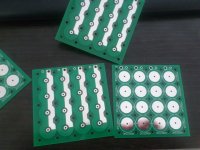
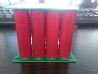
The problem: Finding a suitable battery contact that can solder to the circuit board. The ideal contact would be nickle plated copper to offer excellent conductivity a good mating surface that stays clean and does not corrode.
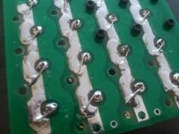
The solution so far: After several different products including designing my own nickel plated copper buttons that I had shipped in from china, I settled on tacks... But not just any type of tacks. These are retail security tacks that are used to pin RFID tags to expensive products. These tacks are flat, are only slightly larger than ideal size and are nickel plated. Importantly, they provide a soldering point for through hole PCB use. They are however made of steel rather than copper, but that can be compensated for by using pads and thick vias. These tacks come in boxes of 1000 and can be had for as low as 3.5 cents each, perfect for a low cost solution.

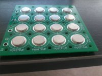
Now on the the biggest and most expensive challenge: How to squeeze those batteries together.
The solution: delrin plastic stands....a forest of them. These stands are 66mm long, and 7.7mm in diameter. This allows a grid of 18650 batteries exactly 18.5mm on center. They are light and very strong. By using a stand on 4 sides of a battery, you can create a very strong contact between the pcb and the battery for every single battery. They are threaded on the top and bottom to allow the use of screws to attach to the pcb boards. These single stands are also very versatile in that they allow an infinite number of possible pcb battery designs. I have had 9 manufactured at a cost of around $300!! just to test how they would work with 4 batteries. Worry not because you will need a lot of these things and that means that a mold will have to be made. A mold will cost about $1000 and after that each piece will be about 30 cents to make. To put that into perspective, if you created a 100 battery solution, you would need a forest of about 120 stands which would cost about $36. They only weight 2.25g each.
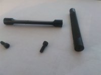
View attachment 5
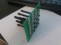
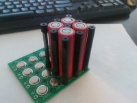
The final product ended up being much stronger than I ever imagined. Even with only 4 batteries and 9 stands the structural integrity was excellent. The stands and batteries themselves act like struts and end up forming a solid immovable brick. I can only imagine the strength of dozens of stands and batteries will be. The contact between the battery and the board is excellent and would be almost impossible to move as more stands and batteries are used. Initially I thought that I would have to use .93" or .124" FR4 board, but my prototype is using .62" and it is definitely strong enough. I was also worried that the delrin plastic stands would strip easily, but they are actually very resilient, and very tough to strip if you use the right length of screw. 5/8" #4 hex machine screws work perfectly. If this project were to continue, I would suggest 3x8mm screws to make it more international friendly.
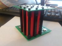
Fusing proved to be a challenge. My initial plan was to use extra small low profile blade fuses like they use on motorcycles. One for each cell but that proved cost prohibitive. After being inspired by the Tesla Motors battery pack, I settled on fuse wire which can be found in Europe. While this approach works, it is far more time consuming to implement than I had imagined. If the project were to go forward, I would suggest ditching this route in favor of designing PCB fuse traces. This will not be an easy task since PCB fuse traces do not allow a lot of consistency and can not be easily repaired. However, I feel it is the only route to allow a low cost easy to produce solution. If a trace is burned away, the customer should use fuse wire to repair it.
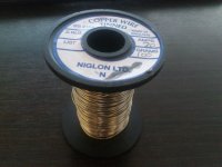
Why am I abandoning this project? Well honestly it worked much better than I ever thought it could. However, as I was putting batteries in I realized how easy it would be for someone to either electrocute themselves, improperly install a battery and severely burn themselves, improperly install a battery and possibly burn down their house. There are tons of scenarios that can end up very bad and the blame will fall not on the customer, but on the kit manufacturer. After watching some 18650 exploding battery videos I decided this project was too much risk for me and I was out. Yes you can limit liability by incorporating and having people sign wavers, but the thought of someone hurting themselves or losing a home because they could not build the battery properly was too much for me to bear. Fortunately there are braver people than me out there and this project might live on. I would be glad to answer any questions.
All my progress is available to purchase at a small fraction of the cost to make plus shipping to a VERY SERIOUS buyer only. Includes all materials and CAD designs and quotes.
.
However, my loss might be the communities gain. After about $500 spent on materials I have come away from the project with some knowledge that could bring about the holy grail of a relatively cheap, extremely strong and capable 18650 solderless battery solution. The only problem is, does anyone really want to spend the extra $3000 it will take to actually fully test the thing and then market it to all the idiots of the battery world who will muck it up and burn down their homes. Then blame you!
OK on to the product. Simply put, just take two printed circuit boards and squeeze some batteries in the middle. Using printed circuit boards provides an easy solution for all the different battery combinations that one can think of. Printed circuit boards are also easily designed and procured from any number of sources for a very reasonable cost in lower quantities. Printed circuit boards also offer a wide array of copper thickness and trace size solutions to handle very high power.


The problem: Finding a suitable battery contact that can solder to the circuit board. The ideal contact would be nickle plated copper to offer excellent conductivity a good mating surface that stays clean and does not corrode.
The solution so far: After several different products including designing my own nickel plated copper buttons that I had shipped in from china, I settled on tacks... But not just any type of tacks. These are retail security tacks that are used to pin RFID tags to expensive products. These tacks are flat, are only slightly larger than ideal size and are nickel plated. Importantly, they provide a soldering point for through hole PCB use. They are however made of steel rather than copper, but that can be compensated for by using pads and thick vias. These tacks come in boxes of 1000 and can be had for as low as 3.5 cents each, perfect for a low cost solution.


Now on the the biggest and most expensive challenge: How to squeeze those batteries together.
The solution: delrin plastic stands....a forest of them. These stands are 66mm long, and 7.7mm in diameter. This allows a grid of 18650 batteries exactly 18.5mm on center. They are light and very strong. By using a stand on 4 sides of a battery, you can create a very strong contact between the pcb and the battery for every single battery. They are threaded on the top and bottom to allow the use of screws to attach to the pcb boards. These single stands are also very versatile in that they allow an infinite number of possible pcb battery designs. I have had 9 manufactured at a cost of around $300!! just to test how they would work with 4 batteries. Worry not because you will need a lot of these things and that means that a mold will have to be made. A mold will cost about $1000 and after that each piece will be about 30 cents to make. To put that into perspective, if you created a 100 battery solution, you would need a forest of about 120 stands which would cost about $36. They only weight 2.25g each.

View attachment 5


The final product ended up being much stronger than I ever imagined. Even with only 4 batteries and 9 stands the structural integrity was excellent. The stands and batteries themselves act like struts and end up forming a solid immovable brick. I can only imagine the strength of dozens of stands and batteries will be. The contact between the battery and the board is excellent and would be almost impossible to move as more stands and batteries are used. Initially I thought that I would have to use .93" or .124" FR4 board, but my prototype is using .62" and it is definitely strong enough. I was also worried that the delrin plastic stands would strip easily, but they are actually very resilient, and very tough to strip if you use the right length of screw. 5/8" #4 hex machine screws work perfectly. If this project were to continue, I would suggest 3x8mm screws to make it more international friendly.

Fusing proved to be a challenge. My initial plan was to use extra small low profile blade fuses like they use on motorcycles. One for each cell but that proved cost prohibitive. After being inspired by the Tesla Motors battery pack, I settled on fuse wire which can be found in Europe. While this approach works, it is far more time consuming to implement than I had imagined. If the project were to go forward, I would suggest ditching this route in favor of designing PCB fuse traces. This will not be an easy task since PCB fuse traces do not allow a lot of consistency and can not be easily repaired. However, I feel it is the only route to allow a low cost easy to produce solution. If a trace is burned away, the customer should use fuse wire to repair it.


Why am I abandoning this project? Well honestly it worked much better than I ever thought it could. However, as I was putting batteries in I realized how easy it would be for someone to either electrocute themselves, improperly install a battery and severely burn themselves, improperly install a battery and possibly burn down their house. There are tons of scenarios that can end up very bad and the blame will fall not on the customer, but on the kit manufacturer. After watching some 18650 exploding battery videos I decided this project was too much risk for me and I was out. Yes you can limit liability by incorporating and having people sign wavers, but the thought of someone hurting themselves or losing a home because they could not build the battery properly was too much for me to bear. Fortunately there are braver people than me out there and this project might live on. I would be glad to answer any questions.
All my progress is available to purchase at a small fraction of the cost to make plus shipping to a VERY SERIOUS buyer only. Includes all materials and CAD designs and quotes.
.


