F&P
100 mW
Hi Guys,
I just joined after reading some great information on this forum.
I am based in Melbourne Australia.
I first posted this on the EV genearl then thought that the motor is more like a bike hub motor, so here it is.
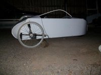
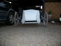
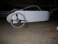
I have for some strange reason, been building a 3 wheeled solar car for the past 2 years part time, after years of working in the solar industry and being facinted with motors running from solar power and sometimes combined with batteries.
View attachment 3
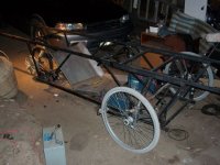
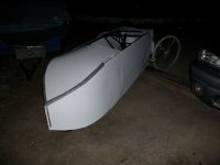
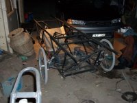
Since the pics above I have cut down the steel extensions to mount solar panels and now just using it as a EV and will make a light weight trailer for the 4 x 80W solar panels. Used cheap corflute for the fairing.
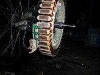
See you tube link of motor running: A bit of a knock due to magnet touching stator slightly.
http://www.youtube.com/watch?v=0GFiTE-2hcs
The motor I wanted for the project was always going to be a multi-pole brushless 3 phase type of motor, as have built many 3phase wind turbines using old Fisher and Paycal (F&P) washing machine motors rewound for higher amps and lower voltages, they also have halls sensors and this I want to talk about later.
Originally Brett White from http://www.ebike.biz in Australia, helped me out with testing some controllers he had with the F&P re-configured motors, as he had also thought that they would make a great Brushless vehicle motor.
It worked the first time I tried a Crystallyte 20A / 48V controller after half guessing the configuration of wires, amazing.
I put it on a large giurls bike with some Nicads I had at 48V / 10Ah, I had is chain drive at nearlyy 1-1 gearing wiht a 27"wheel and it went like a rocket but never reached its full speed as when I tested it wiht a bike speedo i found it was doing about 95kph free wheeling of course.
I then geared it down to about 2-1 and wheel stands became very easy and scarry and speed was 50-60Kph.
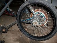
I finshed the solar car based on one rear wheel with a single sided swingarm and the motor's 1" x 10" stainless shaft directly welded into the hub of a BMX 20" wheel with a small motorbike shocker.
The front 2 wheels also used a motorbike shocker for each wheel.
The frame is a trellis type of frame made from 20mm / 1.6mm square steel.
I am using for now 4 x 12V Haze 18Ah gel batts, but will go for lithium when I can offord it.
Weight without solar panles is about 90kg and i only weigh 65kg. Panels are about 7kg each x 4 = 28kg, total with me and panles = 185kg.
Will be using 4 x 85W / 4.9Amp Suntech panels as they are cheap but heavy due to glass.
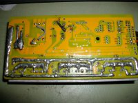
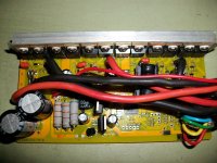
I brought a 72V / 45Amp 12fet, Infineon controller from Keywin and it failed after some driving.
I think the motor had too little resistance at about .1 to .2 Ohms.
Keywin helped me out with a repair and I brought spare IRFB4310 Fets and a spare PCB with all surface mount componenets.
I re-configured another F&P motor as they came in 3 wire sizes being: .6mm latest, .8mm mid and 1mm first model.
I used a .8mm motor re-configured in parallel with about .4 Ohms.
These motors are large, measuring about 12"x 2" (300mm x 50mm) with 42 coils and 56 magnet poles.
the motors come with ferrite magnets I replace them with Neo magnets measuring 10mm / 40mm / 6mm thick.
they have a 1" (30mm) x 12"(300mm) stainless steel shaft which normally connects to the washing machine tub.
I also think the problems I have had with the controllers is that the hall sensors seem to be placed in a different order to what is on the bike hub motors.
I will attach pictures and a short video for you to see what I mean and possibly help me with any problems you guys can see.
I also need help in getting my new infineon 72V / 45A controller working.
Finally i just brought a 1000W (not sure about rating ) bike hub motor and controller from Conhismotors which i know seem a bit dodgey but for $220AU shipped to Melbourne, it was too good to knock back, will tell you how it goes.
See attached picture of motors hall sensor location, different to bike hub motors, any ideas in this??.
F&P Motor stator with hall sensor location.
Matt Lyons (F&P)
My work website: http://www.energymatters.com.au, cheap solar panels etc.
I just joined after reading some great information on this forum.
I am based in Melbourne Australia.
I first posted this on the EV genearl then thought that the motor is more like a bike hub motor, so here it is.
I have for some strange reason, been building a 3 wheeled solar car for the past 2 years part time, after years of working in the solar industry and being facinted with motors running from solar power and sometimes combined with batteries.


View attachment 3

Since the pics above I have cut down the steel extensions to mount solar panels and now just using it as a EV and will make a light weight trailer for the 4 x 80W solar panels. Used cheap corflute for the fairing.


See you tube link of motor running: A bit of a knock due to magnet touching stator slightly.
http://www.youtube.com/watch?v=0GFiTE-2hcs
The motor I wanted for the project was always going to be a multi-pole brushless 3 phase type of motor, as have built many 3phase wind turbines using old Fisher and Paycal (F&P) washing machine motors rewound for higher amps and lower voltages, they also have halls sensors and this I want to talk about later.
Originally Brett White from http://www.ebike.biz in Australia, helped me out with testing some controllers he had with the F&P re-configured motors, as he had also thought that they would make a great Brushless vehicle motor.
It worked the first time I tried a Crystallyte 20A / 48V controller after half guessing the configuration of wires, amazing.
I put it on a large giurls bike with some Nicads I had at 48V / 10Ah, I had is chain drive at nearlyy 1-1 gearing wiht a 27"wheel and it went like a rocket but never reached its full speed as when I tested it wiht a bike speedo i found it was doing about 95kph free wheeling of course.
I then geared it down to about 2-1 and wheel stands became very easy and scarry and speed was 50-60Kph.
I finshed the solar car based on one rear wheel with a single sided swingarm and the motor's 1" x 10" stainless shaft directly welded into the hub of a BMX 20" wheel with a small motorbike shocker.
The front 2 wheels also used a motorbike shocker for each wheel.
The frame is a trellis type of frame made from 20mm / 1.6mm square steel.
I am using for now 4 x 12V Haze 18Ah gel batts, but will go for lithium when I can offord it.
Weight without solar panles is about 90kg and i only weigh 65kg. Panels are about 7kg each x 4 = 28kg, total with me and panles = 185kg.
Will be using 4 x 85W / 4.9Amp Suntech panels as they are cheap but heavy due to glass.
I brought a 72V / 45Amp 12fet, Infineon controller from Keywin and it failed after some driving.
I think the motor had too little resistance at about .1 to .2 Ohms.
Keywin helped me out with a repair and I brought spare IRFB4310 Fets and a spare PCB with all surface mount componenets.
I re-configured another F&P motor as they came in 3 wire sizes being: .6mm latest, .8mm mid and 1mm first model.
I used a .8mm motor re-configured in parallel with about .4 Ohms.
These motors are large, measuring about 12"x 2" (300mm x 50mm) with 42 coils and 56 magnet poles.
the motors come with ferrite magnets I replace them with Neo magnets measuring 10mm / 40mm / 6mm thick.
they have a 1" (30mm) x 12"(300mm) stainless steel shaft which normally connects to the washing machine tub.
I also think the problems I have had with the controllers is that the hall sensors seem to be placed in a different order to what is on the bike hub motors.
I will attach pictures and a short video for you to see what I mean and possibly help me with any problems you guys can see.
I also need help in getting my new infineon 72V / 45A controller working.
Finally i just brought a 1000W (not sure about rating ) bike hub motor and controller from Conhismotors which i know seem a bit dodgey but for $220AU shipped to Melbourne, it was too good to knock back, will tell you how it goes.
See attached picture of motors hall sensor location, different to bike hub motors, any ideas in this??.
F&P Motor stator with hall sensor location.
Matt Lyons (F&P)
My work website: http://www.energymatters.com.au, cheap solar panels etc.


