I want to go 20mph, but i'm stuck

Wesnewell: Alright, well I just realized that on the wiki there is a sort of flow chart below the first flow chart for testing the sensors and phase wires. So I will try all those combos tomorrow.

nutspecial: alright I will keep those suggestions in mind for if all else fails. ahh yes I forgot that happened. In the pic that is a burn mark from after I opened the controller to take pics. I dropped my tiny screwdriver and it shorted right on the shunt and the copper sticking out. It was quite a big spark and scared the $#@! out of me. How would I go about measuring the draw using the multimeter? Also is it normal for the motor to still spin even with the hall sensor unplugged? and I noticed on the hall sensor that the red wire from the controller was going into the black wire on the motor, and the black wire from the controller was going into the red wire on the motor. is that normal or are they switched?

Nelson37: Yeah the flow chart on the wiki should help me with being methodical. I will just need to be patient and spend some time.

Thanks y'all for your help. This thing is quite a pain (literally) and I would never have had any chance of figuring it out. I feel like we are getting close.
 
If I were you, I'd start all over again hooking all the wires color for color, then just follow the phase chart from the top. Shouldn't take more than a few minutes to find the right combo. If it runs real smooth from the start, just jump to the change rotation at the bottom and follow instructions there.
 
As I said before, your jumping round like a headless chicken. You maybe trying to solve the wrong problem. First, you need to identify what's limiting the speed. It could be the motor, the controller or the battery. The speed test that I detailed previously will eliminate many of the possibilities. You have to test and measure your way to a solution, not jump about from one thing to the next trying to guess the answer.

The hall sensor wires must go black to black and red to red. Start with putting that right. Your controller can run both with and without hall sensors, but some motors don';t like to run sensorless.
 
alright so i tested all 36 combinations of the phase and hall wires and this is what i got. the only way for the bike to go forward is for either the blue, green, or yellow phase wire to be connected to the same color and the other to be connected to the opposite color. ex: green to green, blue to yellow and yellow to blue. however. when i have to blue to blue set up, the bike pulls more current than normal and trips the bms in the battery. aside from that, i didnt get any change in speed. so what should be my next step?
 
Test the hall and phase wires for shorts, Test the hall sensor circuit. If you follow the phase chart, and the halls are working right, you have to get the right combo. If your controller will run sensorless, disconnect the hall plug and swap phase wires around until it runs right.
 
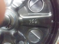
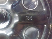
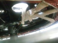
so I added some pics of the inside of my motor. I wasn't able to make the two first pics small so sorry. I wasn't able to get any good pics of the other side inside the motor however it is basically the same except on the inside there is also an engraving of the # "24" and "GM 2014". My question is if the red and black wire are supposed to be just dangling there not connected to anything.
How do i test the hall and phase wires for shorts? It runs without the hall sensors wires unplugged so i will just try swapping the phase wires.
1EnFiaX.jpg
MEpbYyq.jpg

20150916_152237.jpg20150916_152248.jpg20150916_152350.jpg
 
i just tried running the bike without the hall and trying different combos. nothing changed except that I have to have move forward a bit for the motor to start working.
I also noticed on the side of my motor that it says "HBS-36v500w"
(From what i have researched I have a "golden motors" brand motor. hence "GM 2014" on the motor.)
 
I don't know what else to suggest, I'm very new to this also, with only one fairly unique build done.
Time to dig into the forum search - the goog and advanced options are really helpful. There's almost enough info here to build anything 'E' from scratch

Good luck on getting a bit more speed, it does sound like it should be doable with what you have, once properly informed. If not, you'll gain a bunch of knowledge should you choose to modify, build another, or have to troubleshoot and fix your build in the future.

Some flags for any other viewers/commenters:
disconnected wires in hub?
pic of controller where shunt was shorted to a contact?
most importantly, are we sure the kit should achieve more than 15mph in the first place?
 
Go here.
http://goldenmotor.com/
Then select hub motor, scroll down until you find the 36V 500W motor and download the performance chart. As you can see, it's rated at 266rpm minimum on 36V. That just over 20mph in a 26"wheel. If you're only getting 15 mph there's just a few reasons for that. Somethings wired wrong, controller is screwed, you're running motor in reverse mode which the controller would default to a slower speed, etc.,etc. But the most logical reason is wrong phase wiring. I don't know what else to tell you. I ran a GM motor with the same specs on 44.4V and it got close to 25mph. Go to youtube and search for how to test hall sensors and you'll find videos showing you how to do it with a volt meter.
 
Alright so I did two tests: throttle and hall sensor. I got the tutorials from here: http://www.ebikes.ca/learn/troubleshooting.html
For the throttle test I got .8 volts with no throttle and with the throttle it slowly increased up to 3 volts before I could the motor stop spinning faster and from the voltage increased from 3 to 3.5 volts before I throttled all the way however the wheel didn't go any faster.
For the hall sensor test I was supposed to test each sensor from the controller and it should either have about 5 volts or 0 volts. During my tests it was constantly at 5 volts and never changed to 0 which I thing means that either my sequencing is wrong or the hall sensor isn't working. So I switched the combinations of the halls around and even the phase wires around and both but it was always at 5 volts. The tutorial doesn't say what to do if it isn't working but I think I am now going in the right direction.
Also I don't know if I said this already but as I connect the throttle wire from the controller to the throttle the motor jerks a bit as if I activated the throttle. Don't know if the means anything or not.
 
You measure the hall sensors between the black and each colour while you turn the motor backwards slowly. The red should stay steady at 5v. The other three colours should switch on and off. Is that how you tested?
 
It's very unlikely that all three would blow and the 5v still be OK, which is what makes me think that you've measured incorrectly. Unlikely but not impossible! Best to check again.
 
Did you measure the Hall sensor output using the Volts AC scale? You need a meter that can measure peak to peak, not RMS. If you measure DC, it may not read correctly, these are low duty cycle pulse signals. You should be able to read the Hall sensor outputs just by manually spinning the wheel, As others have said, this seems to be a miswire on phases/Hall sensor wiring, unless the Hall sensors have overheated and burned out, which does happen when you overheat your motor.

If I may suggest, buy a tester on ebay for the controller. They run $10 and would tell you what's right and wrong with your controller. Considering the time spent so far, $10 seems pretty cheap.
 
The hall sensor circuit is DC, not AC, and you can't test them by spinning the wheel unless you mean at 1 rpm or less. You don't spin it, you just turn it, very slowly.
https://www.youtube.com/watch?v=efYFOHnXh0E
 
I'm curious is this is solved?

I keep wondering if maybe either the controller or the BMS is current limiting you. The battery spec said 15A continuous, so I assume the BMS limits current to that using a shunt. Is that the problem? Maybe it's current limiting too low. And in the controller, same issue. There is a shunt to measure current, and it had some solder blobs on it like somebody played with it. Is that the problem?

I'm hoping we learn what the problem was, so we can avoid it.
 
Sorry guys I have been busy lately and haven't been able to do much with the bike . So I redid the hall sensor test and no matter what I did (switch phase wires, hall wires, spinning the wheel backwards, forwards, slow, fast, AC, DC) I didn't ever see the voltage drop from 5 volts to 0 or anything in between. They all stayed around 5 volts. Does that mean I should get a new controller? I don't know if it can be the current since all I need is 15 amps and 36 vols to 500 watts. I also used to use a battery that didn't have a BMS on it so it could deliver as much amps as it wants. I also noticed those soldering blobs but those were there when I opened the controller.
 
Ethan102 said:
Sorry guys I have been busy lately and haven't been able to do much with the bike . So I redid the hall sensor test and no matter what I did (switch phase wires, hall wires, spinning the wheel backwards, forwards, slow, fast, AC, DC) I didn't ever see the voltage drop from 5 volts to 0 or anything in between. They all stayed around 5 volts. Does that mean I should get a new controller? I don't know if it can be the current since all I need is 15 amps and 36 vols to 500 watts. I also used to use a battery that didn't have a BMS on it so it could deliver as much amps as it wants. I also noticed those soldering blobs but those were there when I opened the controller.
It is not the controller causing the bad readings on the Hall sensors, if your readings are fact. It sounds like you don't have a ground connection (black) to the Hall sensors, since all three read high only, or the Hall sensors are shorted, burned out. You should get a signal swing from say 1 to 4 volts approximately on each. If you see 5V only, no ground maybe? Check it. This could be bad connector, broken wire, mis connection, many things. Find out. If you ever reversed the red and black wires to the Hall sensors, they may be toast. Is that possible? when you are switching wires around, it's pretty easy to mix up things. Unfortunately, you can burn stuff up doing that. If the Hall sensors are in fact bad, that would be the 3 hall sensors inside the motor, and I think it requires a pretty good tech to replace them.

If it was them, maybe the motor can run sensorless on a controller designed for that. But that's a shot in the dark. Figure out if the Hall sensors work - step one.
 
If you did the test like the youtube video and they all failed, then unplug the hall wires connector, hook a 5-9V battery to the red and black wires, and then test again between the black wire (which should be connected to the neg battery terminal) and each of the hall wires. If they go from ~5-9V to close to 0V when you slowly run the wheel the hall sensor is good and the problems in the controller. The voltage you see will depend on the battery you use minus a little for circuit loss
 
Lookingat the picture of the hall sensors and the combination of the colored wires. Would the firing order be green, yellow, blue ? I'm guessing this by the order of the wires. Then looking inside the controller for the A,B,C firing order. Can we look inside both the motor and controller for a definite order. Meaning an we read this like a map ?
Is the controller still getting hot ? Or hand warm.
Well it doesn't get hot, rap the controller shut with some copper wire a couple turns and solder.
Or could be a euro speed limted controller. Being from China they just could have thrown it in the box to make the order.
 
slowhands said:
If you ever reversed the red and black wires to the Hall sensors, they may be toast. Is that possible?
Well when I first got the ebike, the red and black hall wires were switched but I didn't know until about 2 weeks ago. I switched them to the right order but its probably too late isn't it? :(
 
Ethan102 said:
slowhands said:
If you ever reversed the red and black wires to the Hall sensors, they may be toast. Is that possible?
Well when I first got the ebike, the red and black hall wires were switched but I didn't know until about 2 weeks ago. I switched them to the right order but its probably too late isn't it? :(

It's possibly too late. If power is reversed It only takes a nanosecond to fry semiconductors. If you had red and black reversed ever, it's potentially serious. I say potentially because some Hall Effect Sensors do have a reverse polarity prevention diode on the supply line --- and some don't. But I don't know what exact sensor part is used in your motor. If it had no protection and you ever got power backwards, poof.

Since the Hall sensor outputs seem to be stuck high, and since you have verified they have ground, the sensors "look" bad from here, my educated guess. You need to really figure out for sure if the sensors are good or bad. Definitely measure them and be sure. Bad Hall Effect Sensors prevent correct operation, even with a perfectly working controller.

If the sensors are bad, you have a choice of remedies: repairing the motor or using a controller that runs sensorless, such as a couple of the Infineon's:
http://em3ev.com/store/index.php?route=product/product&path=38&product_id=136
http://em3ev.com/store/index.php?route=product/product&path=38&product_id=135

If it were me, and I did not want to mess with fixing the sensors in the motor (it's delicate work), I'd grab a sensorless controller and hope that solves it. I'd be willing to spend money on a sensorless controller to save time resolving this.

All you would need is the 3 throttle wires to the controller, 2 power wires to the controller, and 3 phase wires to the motor, just those connections. (Actually, you should be testing this now with only those connections, plus the Hall sensor connections.) Things like the brake signal, PAS signal and other optional connections just confuse things. Keep it simple. Do be very careful about the wiring connections, especially the reds and blacks, typically power. You usually don't get second chances with power.

Looking at the ebay feedback on the vendor, this motor and controller seems to be working for a lot of people. So, hate to say it, you probably miswired something and did a little damage --- enough to cripple you to low speed only. The good news is the motor does seem OK, except for the hall sensors If my guess is correct. If my suspicion about the Hall sensors is correct, you can recover, either by fixing the sensors in the motor or going sensorless.
 
Hey guys, I just wanted to bring closure to this thread for anyone else who might have this problem. The solution for me was to buy a new motor since the old one either had a bad hall sensor and prevented it from going 20, or it just wasn't strong enough. I bought a new motor and it works great. Thanks guys for all your help.
 
hey ethan very cool...i am glad the new motor is working out...so what did you get?

the old motor what was the speed wind on it? was it geared or dd?

and you know the old motor...on ebike simulator...it showing around 23 mph...for a q100...doesn't give winding... at 15 amp setting..
250 pound for bike and rider at 1 percent grade drops it to 20..2percent is 18 3 percent grade is 16 mph...4 is 15 mph....
thats at 540 watts power output...

it also doesn't say if your peddling or not with it.....

it gives an option to enter bike rolling resistance of tire...resistance consists of the following parameters:
type of tires
tire pressure
type of surface
number of wheels
mechanical resistance of the vehicle
At the moment, we have determined that for the two-wheel bicycle moving on asphalt with tires pumped up to 3.5 bar and small tread, the coefficient is 0.013. http://www.electricbikesimulator.com/account.php?language=enmi
 
Back
Top