improving MXUS 3000 V2

Allex said:
I believe that 12AWG is sufficient for this motor at least for this particular one. Dont think 10AWG would fit in there.
Agreed. 12AWG (4mm2) through the axle. Splice to bigger wire if you like, once outside the axle.

I managed to get 12AWG PTFE wire through the axle without too much trouble, and the PTFE insulation is far superior to heat shrink tubing.
 
teslanv said:
Allex said:
I believe that 12AWG is sufficient for this motor at least for this particular one. Dont think 10AWG would fit in there.
Agreed. 12AWG (4mm2) through the axle. Splice to bigger wire if you like, once outside the axle.

I managed to get 12AWG PTFE wire through the axle without too much trouble, and the PTFE insulation is far superior to heat shrink tubing.


Also dont forget that the heat shrink soften when hot so it become more fragile when high current is used.

Doc
 
I have measured the diameter of ONE strand of the MXUS 3000 4T from a friend today.

The diameter was 0.0225"

I other words, it's equal to gauge 23.

In that 4T there is 16 of these strands witch is equal to exactly a 11 gauge wire.

In a 3T there is 21 of these strands witch is equal to just a bit bigger than a 10 gauge wire.


The stock wire gauge on the MXUS 3000 is very similar to a 16 or 14 gauge.

It is clear to me that a wire upgrade WOULD improove performance and avoid melting wires and also connectors due to the added wire heat transfer to the connector.


Doc
 
Doctorbass said:
teslanv said:
Allex said:
I believe that 12AWG is sufficient for this motor at least for this particular one. Dont think 10AWG would fit in there.
Agreed. 12AWG (4mm2) through the axle. Splice to bigger wire if you like, once outside the axle.

I managed to get 12AWG PTFE wire through the axle without too much trouble, and the PTFE insulation is far superior to heat shrink tubing.


Also dont forget that the heat shrink soften when hot so it become more fragile when high current is used.

Doc
Thx doc!

The trick is to use moderate current for that particular wire gauge size that you have chosen, then you will not see that heatshrink soften up :) If the wires get hot then they are to thin fpr that power and you need to beef them up.
 
Allex said:
The trick is to use moderate current for that particular wire gauge size that you have chosen, then you will not see that heatshrink soften up :) If the wires get hot then they are to thin fpr that power and you need to beef them up.
I'm curious...what do you define as moderate current? I'm running the same 12awg wires in my HS4080, and was planning on using the max settings the Mini-E will allow.

Cheers
 
Ha, you are not in the risk zone due to a mini. How much will it handle? I will let Doc take this one.
But I will use it(Actually this one is for Rix) for up to 350phase amps in peak, maybe even 400 for very short bursts - al in all, depends on how hot they will get and to be honest I think the motor will get to hot before the insulation on the wires start to give up.
 
Cowardlyduck said:
Allex said:
The trick is to use moderate current for that particular wire gauge size that you have chosen, then you will not see that heatshrink soften up :) If the wires get hot then they are to thin fpr that power and you need to beef them up.
I'm curious...what do you define as moderate current? I'm running the same 12awg wires in my HS4080, and was planning on using the max settings the Mini-E will allow.

Cheers


The ebike.ca motor simulator is pretty accurate about that question: "how long it can handle" ( for the motor)

As for the 12 gauge i have tested it in this video with 100A and 100A continuous in oe of these silicon skin wire is not a problem... but if you replace the skin of that wire by a heat shrink, the heat shrink will fast become very soft and sensitive to every little sharp edges along teh axel and area where it is pinched.

Test at 100A silicon wire gauge 12 and 10 and too small : [youtube]0DhzWPoSYoQ[/youtube]

But as you know if the battery current is 100A the phase wire might get more amp at low speed and high throttle.

Remember that most of teh time the phase wires melt at low speed with alot of stop and go.

Doc

Doc
 
Doctorbass said:
I have measured the diameter of ONE strand of the MXUS 3000 4T from a friend today.

The diameter was 0.0225"

I other words, it's equal to gauge 23.

In that 4T there is 16 of these strands witch is equal to exactly a 11 gauge wire.

In a 3T there is 21 of these strands witch is equal to just a bit bigger than a 10 gauge wire.
Doc


according to the AWG to mm² conversion table:
http://www.elektronik-kompendium.de/sites/kom/0902141.htm
11GA would be 4.15mm² and 10GA 5,26mm², but i cannot confirm this.

i measured the diameter of a single strand to 0,5mm with insualtion chafed off (with insualtion about 0,55mm). this leads to 0,196mm² cross section.
that would be
3,14mm² on 4T
and 4,11mm² on 3T

stock phase wires of MXUS are 13GA so 2,63mm²
 
One nice trick i have found to insert sime silicon and other wires they the axel hole and also the axel slot and against bearing I.D. is to use GREASE!.. Personally i use bicycle bearing grease withc work like a charm. it avoi ddamaging the silicon skin when pulling to it and that it balloon trying to enter to the small space.

I have used the same way to replcace the stock 10 gauge on my Max E for some 8 gauge. The rubber insert on the cover have very limited I.D. and grease made them to go Inside like a glove.

On my old 5303 ( Crystalyte i have used another method: I have maximized the room for 3x 10 gauge and for the hall sensor connections I have used a small flat cable kapton type) ( like the flat flexible conections in our cellphone and picture camera between various small pcb). it is like 0.005" thick and is wide enough to cary 5 6 or 7 flat copper traces. So i have placed the flat cable for the hall on the bottom of the slot and the 3 phase cable sid eto side together on the top, then added some grease to let the bearing to not grip on the silicon skin but to slide easy when inserting the side cover.

Doc
 
I used to use stock harness PTFE 14G and put heatshrink on it for abrasion resistance..not for insulation. I let the PTFE do its work and the heat shrink protect it and slip it back through the axle. I used to do this to free up room for other wires like a temp sensor in 9C type motors
 
I like silicone wire - durable.
But I wonder sometimes if the silicone coating is too much of a thermal insulator. Thoughts?
I think I saw on another thread that the wires would be making about 40 watts of heat each at about 5 kW.
 
Samd said:
I like silicone wire - durable.
But I wonder sometimes if the silicone coating is too much of a thermal insulator. Thoughts?
I think I saw on another thread that the wires would be making about 40 watts of heat each at about 5 kW.


It's me who calculated the thermal dissipatino of the wires. Yes that would be about 40Watts but who drive 5000W continuus?.. so 5kW is more a burst of power for the majority so 40watts per wire too :wink: Silicon is not a good insulator but not a good heat conducter. I wod not care about the heat produced... These are 200 degree C rated and it happened that few time i solder some of these wires , the big tip of my 80Watts solder iron touch the silicon skin and that tip is way over 400 celsius and nothing happen, no melt.. so the heat dissipation become only a matter of power loss... OR SOLDER MELT... yes i saw one of my motor having the solder that melted inside the heat shrink of the junction of the phase wires from the winding and the silicon wires... so i would say yes the silicon can hold the temp form the conductor but not the solder at the end of it!

DOc
 
Cowardlyduck said:
For non power carrying wires, you really don't need much.
I used this wire for my hall sensors, sensor legs, and for my temp sensor wires.
http://www.hobbyking.com/hobbyking/store/__11849__Turnigy_Teflon_Coated_Wire_36AWG_1mtr_Red.html

I did not use it for the 5V wires for the hall sensors as I was a bit worried they might not like it, but it probably would have been fine.

Cheers
Good idea, These wires was used in the 70-90' for wire wrap connections on electronic prototyping
wirewrap_fig7.jpg


Doc
 
The only issue I found with these 36awg wires was stripping them...you can't use normal wire strippers as they are too thin.
I tried burning off the insulation, but that just leaves a messy wire you can't really solder to.

In the end I found the best way was to use my teeth! You just lightly bite down on the end and pull the wire away.
It can take a few attempts, but I usually got a good strip in the end. Just don't swallow the insulation...I'm pretty sure with enough Teflon you can be poisoned. :lol:

They are also surprisingly strong. I tested pulling on some hard with my hands, and they seem very strong for their size.

Cheers
 
Am I the only one who uses CAT5 ethernet cables harvested from the office when it comes to halls? :mrgreen:
 
Doctorbass said:
Yes that would be about 40Watts but who drive 5000W continuus?.. so 5kW is more a burst of power for the majority so 40watts per wire too :wink:
I can't argue with that!
 
Samd said:
Am I the only one who uses CAT5 ethernet cables harvested from the office when it comes to halls? :mrgreen:
I used some CAT5 for my CA on my recumbent build...works well. :)

And for the throttle, 3 speed switch, on/off switch (which is also powering a 7W LED), and Regen, I used an old DVI cable!
P1070317.jpg

P1070318.jpg


But the beauty of the 36awg wire is it's soooooo small. The 6-7 extra wires needed for halls and temp sensors can amount to a good chunk of space...not if you use 36awg wire though. :)


Cheers
 
Doctorbass said:
I have used the same way to replcace the stock 10 gauge on my Max E for some 8 gauge. The rubber insert on the cover have very limited I.D. and grease made them to go Inside like a glove.
pulling silicone wires through tight rubber bushings can be a bone ginding thing! in my case even oil did not help, but than i tried talcum powder (what i always apply on tubes before i put them into the tire) and it worked great 8)
 
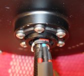
Zip ties can be very charp so I used heatshrink over one before securing it over the axle.
The wires are 12AWG along with hall sensor wires wrapped in heatshrink, pretty tight now!
DSC05661.JPG

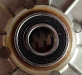
New SKF bearings(6003 on both sides), less play in them and the sealings are tighter, overall a high quality bearing. This motor is going to Rix, so I just do what he tells me to do!
DSC05659.JPG
 
So 12 awg for phase wires, until it comes out of hub, then solder on 10 awg.
For hall wires just leave them stock? I find there connectors at the end to be somewhat flimsy and poor soldering job.
 
Those are 12awg all the way, but first bit is not silicone but heat shrink only.
As for the connectors, use xt150 instead.
You can have the stock hall wires, no problem.
 
great work Allex^^
the red stuff around the wires (i believe for sealant), what is it?
 
Back
Top