jonescg's NEW electric racebike BUILD thread!

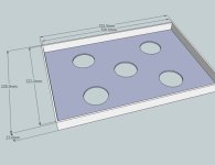
Well I had a good look at the shock and linkage arrangement, and it became clear that I will need to completely re-design the control box. Turns out the box and HV cables won't clear the shock so my idea of laying it diagonally isn't going to cut it.

I can't drill holes into the back of the board either as there are HV traces on the PCB right where the hole would need to go.

So it's time to devise a new, even more compact main control box for the battery...

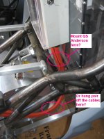
The phase wires to the motor are also in the the path of the shock, but I should be able to push them down and to the side a bit. Most after market shocks use a 77 m OD which is better than the stock 87 mm standard. I'll also have to go for a shock with the reservoir on a hose since there's barely enough room to swing a cat.
 
For anyone who is not full bottle on how the shock linkages work on my bike, I put the swingarm on and recorded a little demonstration.

Short linkage rod:
http://www.youtube.com/watch?v=DSEPoJVPPuw&feature=youtu.be
[youtube]DSEPoJVPPuw[/youtube]
Extended linkage rod:
http://www.youtube.com/watch?v=Cno_kofAWhI&feature=youtu.be
[youtube]Cno_kofAWhI[/youtube]
 
As mentioned above I can't get the main battery control box to fit without moving it up and entering the cables from the back. It looked like it still wouldn't clear the shock mount but as it turned out the cables run either side of it. It's close though. It works out well as the alternative had a pair of HV cables potentially being fouled by the shock spring. The motor phase wires are still a potential point of interference, but I'll get to that in due course.

So I have to get a new PCB made. I can't just drill through the PCB because the left hole goes right through a HV trace :shock: and the HV relay is pretty close to the 12 V contactor and signal wires. It will cost me another couple of hundred dollars but that's sure better than having to modify the frame or design a whole new battery box. When it comes to HV wiring, I will spare no expense making them safe.

box repositioning 001.jpg

box repositioning 004.jpg

Of course this means the box will have to either be sealed with silicone goo or a new polycarb box be made to suit, in order to maintain some level of water resistance. I think the Altronics box is cheaper.
 
jonescg said:
For anyone who is not full bottle on how the shock linkages work on my bike, I put the swingarm on and recorded a little demonstration.

So that linkage rod has an adjustable length? I like that idea and that may be reason enough for me to try a multi-link suspension sometime. Your bike is shaping up nicely.
 
Yeah John it's able to be extended out to about 138 mm and as short as 96 mm. I also have a different linkage plate which put the lower shock mount a bit higher, meaning a lower travel:compression ratio. It's very adjustable, which is a very valuable thing.

Its a shame I can't just use an off-the shelf shock, but 250 mm - 260 mm is all I have to work with, and that's a custom job already. I really need to source a set of Gixxer wheels and get this thing sitting at ride height.
 
SO today I decided to mount the motor into the frame. First I had to pull the swingarm pins out. There is no thread on the inside of the pins, so I needed to 'pull' them out somehow. Solution - a 12 mm Dynabolt :)

Next step was to bolt the motor plates on. Turns out you can't drop the motor out and leave the plates in place as the outrunner bearing and shaft won't clear it. Not a big deal though - just have plenty of blocks and a jack handy.

Motorassembly001.JPG

Win #1 - the motor plates fit perfectly.

Then I noticed that the thrust bearings were exposed to the elements, and probably needed some kind of covering. So I cut a bicycle tube up and slipped them over the receiving end of the pin assembly. Perfect!

Dustcover_zpsc4c31ce9.JPG

Win #2 - the dust covers work!

Then I had to muscle the motor over to the bike and mount it in place. A bit tough on your own but easy with another modestly strong person. I found it easy to attach the rod ends first and then pull the motor up to the swing arm assemblies. If you're interested, this is what the swing arm pivot assembly uses for bearings.
Motorassembly002_zpsc588fc9f.JPG

Motorassembly005_zps888700c4.JPG

Win #3 - the motor fits!

My real concern was the cable run. As it turns out, 50 mm2 cable can be held down close to the motor and still clear the shock, but I will still put a composite cover over the cables and hold them down firmly.

CablerunRHS_zps05d76120.JPG

Cablerun_zpsa4d1d503.JPG

Motorassembly009_zps773e5997.JPG

Win #4 - the cables are clear!

I also inspected the chain run, now that the motor and output shaft were shuffled across to line up. The outrunner bearing was essential as there would have been some pretty serious force on that shaft at 40 mm.

ChainRun_zps3f323a5e.JPG

Win #5 - chain run is clear and straight!

So I picked the whole lot up and put it on the table. It was a heavy setup; the motor and plates weigh in at 50 kg, so there's an easy 5 kg worth of ally that can be removed from the plates. The swingarm is 5 kg, and I'm guessing here, but I think the frame is about 30 kg. While it was up there I decided to position the ZX10 fairings to see how it all looks. Pretty hawt!

VoltronEvoLHSrear_zps0eeb891c.JPG

VoltronEvoLHS_zpsde0135fc.JPG


Win #6 - it looks pretty fine!

Now I need to find some Gixxer wheels, but importantly I need to get a rear brake assembly sorted. I really don't want to, and maybe the rules will permit me to use regen instead of a brake? It really depends on what the local racing scrutineers want, but I think eFXC / TTXGP are cool with regen only.
 
When words aren't enough.
SIMON-COWELL-HAPPY-GIF.gif
 
~395 mm diameter, 115 mm long. The 10 mm motor plates make it look bigger, but they also serve to soak some heat away too.
 
holy dooley.....

Theres going to be a gyroscopic effect from the motor - do you reckon this could be an issue?? I remember having a toy motorcycle with a rip chord and a flywheel - holding it in your hands and giving it a rip - there was substantial gyro forces. It might want to straight line - do you think??
 
I don't think the effect will be very strong, but certainly there. Remember Moto Guzzi bikes had a strange lurch to the right when you blipped the throttle? I don't think it will be that bad. The rotor is only 20 mm thick and about 350 mm in diameter, and it's only going to be spinning at 5000 rpm at the end of a long straight. Plus (a physicist might correct me here) the deceleration of the rotor will change that vector somewhat too...
 
jonescg said:
I don't think the effect will be very strong, but certainly there. Remember Moto Guzzi bikes had a strange lurch to the right when you blipped the throttle? I don't think it will be that bad. The rotor is only 20 mm thick and about 350 mm in diameter, and it's only going to be spinning at 5000 rpm at the end of a long straight. Plus (a physicist might correct me here) the deceleration of the rotor will change that vector somewhat too...

It really depends on how much the rotor weighs and it's mass diameter (circular center of mass). Inertia = mass * (radius^2)/2 So the larger diameter does play a large role. I don't think it will be much of a problem thou, never noticed anything with the EMRAX which is lightweight, but has a larger mass diameter because its and outrunner. I'm not sure how to go from inertia to gryo force unfortunately. googling it now
 
Given the weight of the typical crank in a motorcycle revving much faster than any electric motor I doubt there would ever be any more gyroscopic effect than any regular bike.
 
Not a lot to report, except I now have my HUET/BOSIET ticket which allows me to work safely offshore. Fingers crossed I can be out at sea by the end of October steering ROVs :D

Today I decided to drill and countersink the holes for the battery main control box. I also need to start thinking about the battery bulkheads, or some kind of fixture which holds it down. Should I highside, the bike will go a-tumbling and I don't want the back to separate from the bike.

I have a few attachment points, notably the ones in front and behind the pack:
Motorassembly009_zps773e5997.jpg


LHS Rear mount from above:
Battery supports 002.jpg

LHS Front mount from above:
Battery supports 003.jpg

I'm thinking two struts front and back which sit across the bike and protrude far enough to sit atop a ledge which I will fix to the front and rear walls of the battery pack. The pack will be prevented form moving laterally by an aluminium tray in the base and four channels on each corner to guide it in.

Sure, it won't be 'quick release' but it will only be four bolts and a hoist.

Hope to have some pics of the box in it's new position tomorrow.
 
Today I finally re-installed the main control box. I had to make a couple of L shaped busbars which go from the final battery terminals to the inside of the box. I had to get clever with the dremmel, followed by lots of cutting, drilling and filing, but I got it to work. I soldered the precharge resistors in and secured them in place with cable ties. I also put a D-sub plug in place with the LED lights in parallel. This way I can run a duplicate set of LEDs on the dash board, but should I be doing any testing on the bench I can still see the LEDs there too. The last thing I had to install was a 5 pin microphone jack for the shunt and voltage divider leads. This means the shunt sensors are connected to the HV circuit, which is not ideal but unavoidable. I will be running the heavily divided positive up to the Cycle Analyst and using the external Vsense features. I need to find some orange conduit for that. As a result the Cycle Analyst's 12 V supply will have to go through an isolated DC/DC converter.

The battery isn't looking too bad now, and the tank cover is going to have to cover everything as tastefully as possible. I'll get someone else to make that up for me :) Cause I frocking hate fibreglassing. I'm still yet to buy the BMS, because there's a good $1500 already, but it should all come together pretty fast.

On the actual motorcycle side of things, progress has been slow. However I did order a Ducati 900ss rear brake calliper mount and associated master cylinder mount and foot pedal. Not sure how useful these will be, but the mount is essential. This means I need to use a Ducati 900ss rear wheel and brake setup. From behind this bike will prettymuch look like a Ducati, but from the side it will look like a ZX-10.

I'm thinking of getting some after market rearsets like these ones from the UK. But $300? Yeah well, motorbikes aren't cheap.

Then I need to find some clip-ons, brake levers (hmm, rear brake on the handlebars?) and get that shock/linkage sorted out. My list of big ticket items grows daily... I really hope I get work soon :(
 
Well, what do you do when you haven't made any real progress to boast about? You do some mock-ups and take pictures of it :) I mostly wanted to see how the wheel base looks relative to the height of the battery pack and the width of the bike. It ain't too bad actually. I was worried that the battery pack would sit too high, but I think it's just okay.

Latest mockup 001.jpg

View attachment 3

Latest mockup 004.jpg

Latest mockup 005.jpg

The battery pack is prettymuch done just waiting on cells. I can also start to look around for a big waterproof Anderson-style connector from the pack to the inverter. I will get the guys at EV-Shop to weld up an aluminium tray to locate the base of the battery pack. Then I can start working on the pack locking mechanism.
 

Attachments

  • battery pack retainer.jpg
    battery pack retainer.jpg
    23 KB · Views: 3,456
jonescg said:
Well, what do you do when you haven't made any real progress to boast about?
Dude what you are doing is not easy. I know what its like to build something like this from the start. I LOVE it though its looking awesome! I think I might do the plastic battery box for the CBR 250r IM doing next.
 
Danny Pottage (aka Potz) gifted me some rearsets from a CBR600. They really only fit in one spot, but it looks alright to me. I don't think they will hit the deck before the fairings.


rearsets 002.jpg
 
Nice that you've got lots of holes to put the rearsets in. Are they far back enough for you to get into a full tuck?

Do you have a list or spreadsheet of parts you need? Perhaps E-S members have some of the smaller bits you'll need.

A few obvious ones like handlebars, wheels and brakes stand out :)
 
It actually feels pretty comfortable where it is right now, but I will just aim to get it rolling and see what can be changed in good time. The wheels will be the next major (affordable) purchase, so if you know anyone with a K7 GSXR front wheel in good working order, let me know! I think a Ducati rear will work out easiest, but I still need to source some replacement bearings now that the axle is 20 mm in diameter instead of 17.

Otherwise, I need GSXR clip-ons, brake levers and master cylinders, braided lines, callipers and pads. I will try to fit a nice big radiator up front too. I have finished welding up the battery hoist from recycled steel, but will post that in good time.
 
Made some progress on the battery mounts today. I had been trying to work out what the best system would be for securing the battery inside the bike. Perhaps the more elegant systems would involve welding stuff to the frame, which I was particularly adverse to. That costs money, and I wouldn't dare do it myself. So I thought I would make use of the 10 mm sleeves Randy had welded into the lower frame rail.

I had to position the battery pack roughly where I want it to reside, and measure the distances between the holes and the side of the pack. I estimated the sleeve to be installed at about 30 degrees off vertical, so I could start to line up a bit of a shape. Google Sketchup did the rest and I came up with a system that uses a couple of ledges which will hold a 10 mm stud with a pin hole.

rear battery mounts.jpg

A bit of cutting, grinding, welding and slag chipping later, I came up with this:

rear battery mounts made 001.jpg

rear battery mounts made 002.jpg

I welded a 195 mm spacer between them to make sure they were a bit more solid once bolted in place. I need to get some longer pan head bolts and Nylock nuts for them, but in the meantime you can see how the pack will sit. I'll glue and screw (countersunk from the other side ;)) some 10 mm thick ledges with 10 mm vertical holes to locate the studs. They are really there to provide forwards-backwards support, and a limited amount of side to side. The front lugs will do a good job of all directions, and the locating tray at the base will take care of the rest.

Next step is to do the same for the front frame rails. This should be much easier as I can make use of the battery cradle frame bolts. It won't be a quick release pack, but it will be a "one-minute removal" pack. If I am charging this pack and it all goes bad, I would prefer it to happen away from the rest of the bike.
 
Today I started looking at all of the relatively inexpensive things I can do to get this bike on the road. I made a list about two pages long, and broke it up into 'cheap', 'expensive' and 'wait till you've done a few shifts offshore'.

ToDo_quickswap 001.jpg

One of the first jobs was to get the lower battery locating tray built and welded. My mate Dan over in Brisbane has been getting good with the TIG so he offered to donate his time to the cause. I lay each part out on the cradle frame rails and used sticky tape to determine their position. Once I knew it was going to fit, I clamped each piece of ally and put M3 screws and nut through to keep it firmly in place. Then it was a matter of mailing it over to Brisbane for TIGing.

Tray 002.jpg

This tray simply bolts into the Rivnuts on the lower frame rails. There is a bit of clearance for the pack where I might put some thin rubber or something, mostly to stop any needless chaffing.

I have come to wonder about connecting the battery output cables to the inverter. Since being able to remove the pack quickly is important, I have been wondering if I could mount a 175 A Anderson connector on the frame and the other on the pack, so that when I lower the pack into position it simply clicks in ready to go. The alternative is to have the connector further along the cable, and it requires a human to connect and disconnect them from behind the fairings before un-pinning the pack and hoisting out. I like the quick-swap idea, but it means alignment is going to become a bit more important. Any thoughts?

Otherwise I have found some ZX10 fairing mounts I can order online and have them fit the bike perfectly.
http://www.ebay.com.au/itm/KAWASAKI-ZX10R-20112012-Upper-Stay-Fairing-Bracket-New-/320936150523

And I learned that getting a few sprockets made up and splined to suit the epic 1.75" output shaft will cost me a couple of hundred bucks. I can't get this done until I have a rear wheel and I can determine the necessary sprocket offset.

So it's slowly coming together. I have built a battery for Entecho using the LiPo cells and it looks great. I think I will to my battery assembly at Entecho since they have the room and clean space to commit to such a huge undertaking.

Next in line is the copper bus links going from each 175 V pack to the switchyard...
 

Attachments

  • ToDo_quickswap 002.jpg
    ToDo_quickswap 002.jpg
    102.6 KB · Views: 3,013
Back
Top